
Hello Engineers, It’s lazy especially when you are tired to go and turn ON/OFF the lights, fans, etc. So, today I am going to present an infrared remote control switch circuit. This is a simple circuit using a CD4017 decade counter IC, a pair of IR sender(encoder) & IR receiver, and relay. This infrared remote control switch circuit lets you control ac devices with an IR remote. The circuit and the receiver, both are shown here. So, let’s get started with our infrared remote control switch. This one is a low distance, to check a better design flow up the link in between the content.
IC CD4017
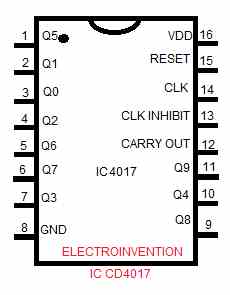
IC CD4017 is a 16 pin CMOS decade counter IC that is also a decoder. This is a suitable IC for Lower counting range applications and this small IC is quite good at many low range counting devices. It has outputs from Q0 to Q9 (10 counts). It has the capability to turn on 10 different outputs sequentially with the desired set time and reset. This IC can be used in various circuits/devices like low range counters, LED light chaser, LED matrix, Infrared Remote control switch circuit(that we are going to discuss today), binary counter/decoder, delay timers, etc.
This IC has 3 Input pins and 10 output pins respectively
INPUT PINS:-
- RESET – The work of reset PIN is the same as the name and is to reset the counter to 0. If we want only 4 counts then the 5th pin’s output must be connected to the 15th pin. So each time after pin 4 output the counter will be reset and start again.
- CLK – Pin 14 which is clock pulse. This pin that gives output to the output pins in a sequential fashion whenever this pin’s input goes high(1).
- CLK INHIBIT – Pin 13 which is clock inhibit pin. It is used to switch ON/OFF the IC. To Switch the counter ON, we need to keep pin 13 high, then it won’t focus on clock pulse and counter stops.
OUTPUT PINS – These pins are from Q0 TO Q9 a total of 10 output pins to provide output sequential output. Each time the clock goes high, we get output from one pin. Pin 3(Q0) provides first-time output then pin2 (Q1)…..
The GROUND pin – PIN 8 Simply for ground and needs no explanation.
CARRY OUT PIN – Used to carry and sum like when connecting multiple ICs with the previous state.
IR LED + Photodiode pair
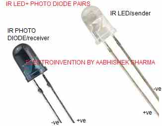
IR led is an infrared Diode that is given power just like a normal LED and current flows in it just like a diode. The electron flow to the side of the hole in order to flow, they shed energy in the form of photons that produces light. Infrared diodes have a package that is opaque to visible light but transparent to infrared. Infrared lights are not visible to the human eyes or visible light but is visible to cameras. IR light is very similar to visible light, except that it has a wide wavelength. This makes it not visible to human eyes.
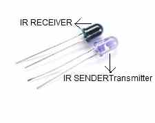
IR RECEIVER/sensor/photodiode
IR sensor or receiver senses IR light, IR radiation emitted by IR Emitter sender transmitter. When the IR diode receives the signals its resistance starts becoming less and when full light falls over it, its resistance is lowest and starts acting like a closed switch. It is basically connected reversed biased.
The Circuit Diagram
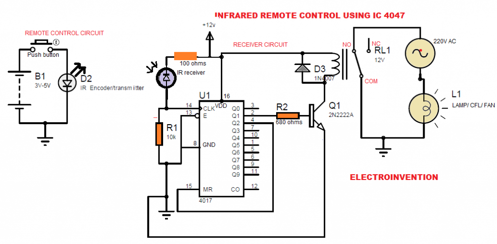
Materials and components:-
- U1 CD4017 IC – 1pcs
- 1 IR receiver and IR led/IR emitter set
- Q1 transistor 2N2222A or BC 547 – 1ps
- 12V Relay-1pcs
- D3 1N4007-1pcs
- R1 10K,
- R2 680 Ohms-1 K (1pcs)
- 100 ohms resistor before IR receiver
- Push-button
- PCB 1 pcs
Working
When the button on the remote is pressed then IR LED emits the IR light. When the IR diode receives the signals its resistance starts becoming less and when full light falls over it, its resistance is lowest and starts acting like a closed switch. This diode is connected in reverse biased The clock inhibits Pin(13) in this is always low as connected to ground so always counter is on. When the receiver receives signal its resistance is 0 and the clock pin receives its first high signal and then the photodiode again starts behaving like diode as soon as the remote button is released and the clock is low again. The counter stops in the hold state where pin 3 (Q0) giving output (but no device connected).
A better long distance circuit is here.
When the remote button is pressed&released again, then the clock is high for a moment and pin2(Q1) latch is ON. This time the Pin 2 (Q1) is giving latch output to the relay and relay connects 220v device to the mains supply. Next time again button pressed and released, the clock pin receives the high signal for once and then Q2 which is on pin4 goes ON. But the pin 4 is connected to pin 15 which is reset and counter restart on Q0. So, the device is turned off as Q1 is off. Each time button pressed and released, the same process is repeated.
This is how the IC and this circuit works.
I hope you guys liked this circuit. If you liked it then please comment it below.
Get a more advanced and better long-distance IR remote control circuit click here.
This is a type of sequential circuit, right? Since it works on the feedback system
Can this circuit run on 5 volts and using a 5v relay. What changes would I have to make to run this on 5 volts?
Hello Srijan, thanks for visiting. Yes, you can use 5v for the circuit but then you need to use a 5v 2A supply with a 5v relay. I suggest use this circuit in the link here https://www.electroinvention.co.in/infrared-remote-control-using-tsop1738 for better results and can be used for long-distance transmission.
ok. here you build both transmitter and receiver? intereasting
Hello Bruno, yes, I did. It was just basic one for basic control and short distance. But the, better one is https://www.electroinvention.co.in/infrared-remote-control-using-tsop1738 due to its long-distance receiving range and can be controlled using most TV remotes.
Good Work sir g
Hi hamid ,thanks for visiting .keep in touch.