
Hello Engineers. Most of the time controlling Lights, Fans, and other electrical devices are cool and very helpful. Especially, when you are tired or busy at some other work. It feels like having a remote control for everything to be controlled with the same remote. So, today I am going to discuss a Long-distance Infrared remote control switch circuit. This circuit is employing an IC4017 and a TSOP1738 IR receiver that can be controlled using any TV remote control. So, let’s get started wit our Infrared remote control switch using the TSOP1738 IR receiver. An infrared remote control switch circuit for controlling AC domestic appliances by your TV remote.
TSOP1738
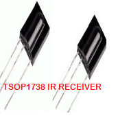
TSOP 1738 IR RECEIVER is a 3-terminal infrared receiver sensor. PIN diode and preamplifier are assembled on the lead frame.
This IR sensor module is consisting of a PIN diode and a preamplifier that is embedded into a single package. The output of TSOP is active low and it gives +5V in the off state. TSOP1738 is used in a variety of applications like TVs, music systems, car stereos, DVD players, etc. When IR waves, from a source, with a center frequency of 38 kHz incident on it, its output goes low.
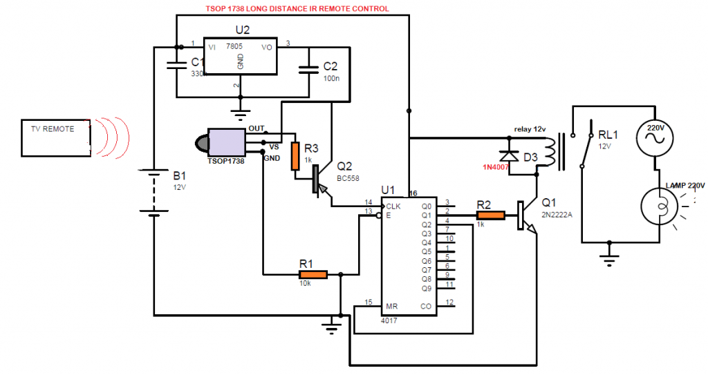
Circuit Diagram
Components
- C1 0.33uf – 1pcs
- C2 0.1uf – 1pc
- U1 IC 4017
- U2 LM7805
- TSOP1738
- R1 10K
- R2,R3 1K – 2pcS
- Relay 12v
- Q1 2N2222A -1pc
- Q2 BC548 -1pc
- D3(diode across relay) 1N4007 -1pc
- PCB
The circuit shown above is quite similar to simple IC cd4017 IR remote control that I have posted here earlier. The difference with this circuit is the TSOP1738 IR sensor and its long-distance range. The older circuit was capable only till a range of 2-3 feets distance and that’s not at all much useful. But this circuit shown above can be used for longer distances up to 20 feet. It can be controlled using any TV remote as most of the tv remotes have a matching frequency of 38khz.
To understand how to use IC CD4017 here in detail, refer to the article click here. The output of the IR Receiver is a decoded output of the signal from Remote control. Whenever a button is pressed on the remote, it transmits modulated Infrared Signals. When the IR light signal is detected by the IR Receiver TSOP 1738 it gives demodulated output via the output pin, pin(3) connected to the R3. The transistor output goes to the IC’s pin 14 i.e clock pin
This output is connected to the Transistor BC548 transistor’s base making it turn ON. When the remote button is pressed&released again, then the clock is high for a moment and pin2(Q1) latch is ON. This time the Pin 2 (Q1) is giving latch output to the relay and relay connects 220v device to the mains supply.
Next time again button pressed and released, the clock pin receives the high signal for once and then Q2 which is on pin4 goes ON. But the pin 4 is connected to pin 15 which is reset and counter restart on Q0. So, the device is turned off as Q1 is off. Each time button pressed and released, the same process is repeated.
I hope you guys liked this circuit and for any kind of queries, you can ask me in comments.
Thanks, If you like my content then you can subscribe to our newsletter feed to get the latest post updates.
much simplified and understandable. I built this circuit some years back and it works till today. thanks
Hello Buddy Bruno, thanks for visiting. Glad you like it.