
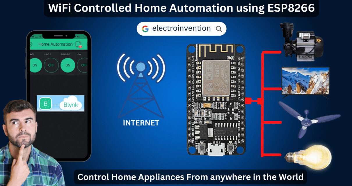
Life Quality has highly been upgraded due to the latest technologies, Home automation has made it easier to remotely control our home appliances with our smartphones via WiFi Connectivity. Wifi Controlled Home Automation allows us to easily control our home devices and security systems via Wifi or Internet connectivity. Here we will be discussing WiFi-controlled Home Automaton using ESP8266 Node MCU.
The ESP8266 is a powerful Wi-Fi connectivity-based microcontroller that can be used to create home automation systems. ESP8266 is a low-cost development board, it is now possible to control home appliances with a simple Wi-Fi or Internet.
With the NodeMCU, users can create an efficient and secure home automation system that can be managed and monitored remotely. In today’s project, there is no need to have Node Mcu and a smartphone connected to the same Wi-Fi connection.
Let’s make something useful today with detailed Circuit explanation, Code, and Videos.
Components and Software Required
- ESP8266 Node MCU – 1pc
- Buy 4 Channel Relay Module – 1pc
- BreadBoard (Optional)
- Wires, Switches.
- 5V Power Supply (USB or external)
- Softwares
- Arduino IDE( To program ESP8266)
- Blynk App
Blynk App Setup – WiFi Controlled Home Automation system
Blynk is a powerful IoT-based platform that allows users to create custom IoT-based applications to integrate IoT-based WiFi Enabled MCUs like ESP8266, and Raspberry Pi, with other home appliances. It provides an easy-to-use interface to quickly build app-based IoT Projects.

The Blynk app also allows users to control their projects from anywhere in the world. It utilizes a drag-and-drop user interface, making it easy for users to create their own apps in minutes. Additionally, the Blynk app features a wide range of widgets enabling users to monitor their projects, send data from their devices to the cloud, and receive data from the cloud to their devices.
How to Configure Blynk for Home Automation?
- Download the Blynk app from the App Store or Google Play Store and create an account.
- Create a new project by clicking the “🔧” icon in the top-right corner of the screen.
- Choose the hardware device you will be using (e.g. Arduino, Raspberry Pi, etc.) and the connection type (e.g. Wi-Fi, Bluetooth, etc.).
- Check your email for the auth token that was automatically generated and sent to you by Blynk. Copy the auth token (in the email, look for the hyperlink as “here”) and save it for later usage.
- In the Blynk app, again by clicking
- After creating the project, you will be directed to the main screen where you can start designing your app’s user interface.
- Click the “+” icon in the top-right corner of the screen to add a new widget.
- Choose the type of widget you want to add to your app (e.g. button, slider, gauge, etc.).
- Customize the widget’s properties, such as the label, color, and pin assignment. For Detailed Configuration settings, check the detailed video.
Wifi Controlled Home Automation Circuit
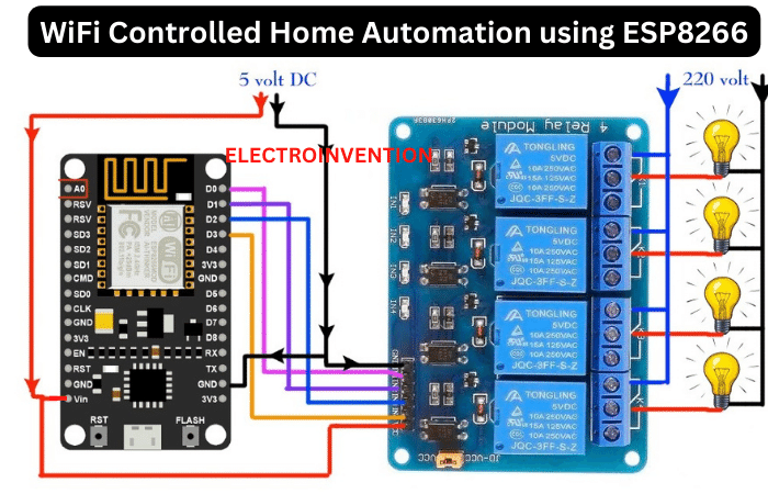
Our Circuit is Simple and easy with having the Node MCU and the Relay Module a 5V DC Supply and Ground in Common. You can also connect a 5V Input from a mobile phone charger.
Here, ESP8266 MCU’s Digital PINs D0, D1, D2, and D3 are connected to the Relay module’s PINs IN1, IN2, IN3, and IN4 respectively. An Input of +5V DC goes in common with the Vin of our microcontroller and VCC of the relay module.
On the other end, the relay Terminals are connected to 4 different Loads with the NO(Normally Open) Pins of all relays in common with the AC Supply and COM PIN of each relay connected to a separate device.
Let’s move further to our code and programming of the ESP8266 module.
Code – Home automation with ESP8266 & Blynk
// wifi controlled home automation using Blynk App & ESP8266
#define BLYNK_TEMPLATE_ID "YourTemplateId" //blynk template ID
#define BLYNK_TEMPLATE_NAME "YourTemplateName " //blynk template  name
#define BLYNK_AUTH_TOKEN "4ANo-vG6TpPOvyXdbZgxBBLCVz976NmB" // enter your blynk auth token

#define BLYNK_PRINT Serial
#include <gpio.h>
#include <ESP8266WiFi.h>
#include <BlynkSimpleEsp8266.h>

char auth[] = BLYNK_AUTH_TOKEN;

char ssid[] = "YouWifiName"; // Your Wifi Name
char pass[] = "YourWifiPasword"; // Your Wifi Password

//in the below code, we have set all values reverse
//For value==1, digitalWrite is "LOW" as the realy module is active "LOW" to turn device ON.
//For value==0, digitalWrite is "HIGH" as Optocoupler based relay is turned OFF when HIGH Input is given
BLYNK_WRITE(V1)
{
  int value = param.asInt();
  Serial.println(value);
  if(value == 1)
  {
    digitalWrite(D0, LOW);
    Serial.println("LED ON"); //Setting Digital PIN as LOW to turn ON Device if relay module is "active low"
  }
  if(value == 0)
  {
     digitalWrite(D0, HIGH);
     Serial.println("LED OFF");//Setting Digital PIN as HIGH to turn OFF Device if relay module is "active low"
  }
}

BLYNK_WRITE(V2)
{
  int value = param.asInt();
  Serial.println(value);
  if(value == 1)
  {
    digitalWrite(D1, LOW);
    Serial.println("LED ON");
  }
  if(value == 0)
  {
     digitalWrite(D1, HIGH);
     Serial.println("LED OFF");
  }
}

BLYNK_WRITE(V3)
{
  int value = param.asInt();
  Serial.println(value);
  if(value == 1)
  {
    digitalWrite(D2, LOW);
    Serial.println("LED ON");
  }
  if(value == 0)
  {
     digitalWrite(D2, HIGH);
     Serial.println("LED OFF");
  }
}

BLYNK_WRITE(V4)
{
  int value = param.asInt();
  Serial.println(value);
  if(value == 1)
  {
    digitalWrite(D3, LOW);
    Serial.println("LED ON");
  }
  if(value == 0)
  {
     digitalWrite(D3, HIGH);
     Serial.println("LED OFF");
  }
}


void setup()
{
  Serial.begin(115200);
  Blynk.begin(auth, ssid, pass);
  pinMode(D0,OUTPUT); //GPIO 16 (equivalent to PIN 16 of Arduino)
  pinMode(D1,OUTPUT); //GPIO 05 (equivalent to PIN 05 of Arduino)
  pinMode(D2,OUTPUT);//GPIO 04 (equivalent to PIN 16 of Arduino)
  pinMode(D3,OUTPUT);//GPIO 00 (equivalent to PIN 00 of Arduino)
}

void loop()
{
  Blynk.run();
}
Resolving the GPIO PIN Errors: ESP8266 GPIO PINs for Arduino IDE
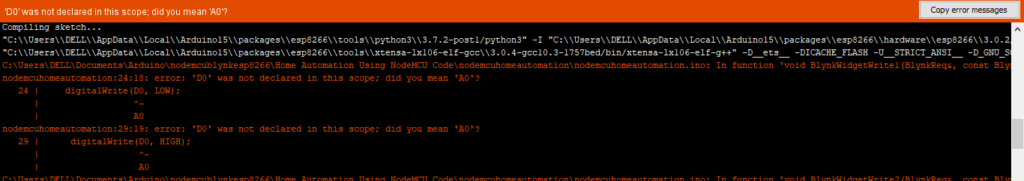
If you are facing any of the errors as listed in the image above, Please refer to the below Pinouts as GPIO PINs. Just change each Digital Pin of ESP8266 from the code to its equivalent GPIO. For eg.
- for D0, write 16
- for D1, write 05
- For D2, write 04
- For D3, write 00

Complete Video Tutorial
If You liked our content and find it helpful, then please do share it with your friends. Also, subscribe to our newsletter for the latest updates. Comment below for any queries.
One Reply to “Wifi Controlled Home Automation using ESP8266 Node MCU”