
Hello Engineers. Here is a quick guide to program Arduino pro mini with FTDI, How to program Arduino Pro Mini? We will use FT232RL USB To Serial UART Module. Also a complete guide on how to use an Arduino pro mini? This tiny Arduino Pro Mini(3.3 or 5V) doesn’t come with Any USB port and USB to Serial UART interface to work with. For this, we need an FTDI module. Here is the Complete Guide to getting started with Arduino Pro Mini. Now, What is an FTDI module?
So, let’s go to our quick guide to using Arduino pro mini with an FTDI module.
What is FTDI? FTDI Module – FTDI Driver
an FTDI Chip module makes it easier for us to interface a microcontroller device with our computer through a USB cable. An FTDI chip helps us interface microcontrollers with PC by converting USB signals to UART signals understood by microcontroller ICs.
FTDI chip is an interface between the Computer’s USB and the other hardware devices eg an Arduino to allow Serial Bus communication with the device and a programmable semiconductor chip(eg microcontroller).
There are different FTDI Chips provided by Future Technology Devices International(a private organization providing specialized solutions for Serial Bus communication Technology).

The one we are going to use here is FT232RL USB to Serial UART Converter module.
Materials Required
- Arduino Pro Mini 3.3V/5V -1Pc
- FT232RL USB to Serial UART Converter module -1Pc
- LEDs (red)
- R1 100 R
- Jumpers
- Breadboard (optional)
- Software Tools-Arduino.IDE Download Here
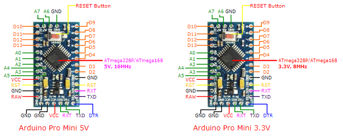
Arduino Pro Mini 3.3v/5v Pinout:-
Circuit Diagram to program Arduino Pro Mini with FTDI FT232RL

To Program an Arduino Pro mini-board, which doesn’t come with any onboard USB port, we need a USB to TTL UART converter module. With the help of FT232RL, we will be able to interface an Arduino pro mini with our PC’s USB Port.
- VCC Pin of FTDI is connected to the VCC Arduino Pro-Mini to Power it (Make Sure to Set the Jumper to 3.3v or 5v according to your Arduino Pro-Mini Specifications)
- The GND of FTDI is connected to the GND/BLK of Pro-Mini & also connected with CTS(Clear To Send) PIn as we don’t need it here it should be connected to 0V(ground)
- Tx(Transmit Signal) Pin is for transmitting the Data and Rx(Receive Signal) is for Receiving the Data, So the TX of FTDI will be connected to the Rx of Arduino Pro-Mini and the Rx of FTDI will be connected to the TX of Arduino Pro-Mini so the FTDI and pro mini can transfer and receive the Serial Data/signal
- DTR(Data Terminal Ready) of FTDI will be connected to the DTR pin of Arduino Pro-Mini to RESET the Pro-Mini for Programming
Demo Code to program Arduino pro mini board
//simple led blinking and serial monitor program
//to demonstrate how to use arduino pro mini
//and program it with FT232RL FTDI programmer
void setup() {
    Serial.begin(9600);
    pinMode(LED_BUILTIN, OUTPUT);
}
void loop() {
  digitalWrite(LED_BUILTIN, HIGH);
  Serial.println("Hello World");
  delay(500);
  digitalWrite(LED_BUILTIN, LOW);
  Serial.println("Hello World");
  delay(500);
}
Looking at code from Line 1 there is a function used “void setup()” explained below:-
“void setup()”, a void is the keyword to used in declaring functions with Arduino.ide. “setup()” is an inbuilt function that is at the start of the Arduino sketch( in Arduino.ide, a program code is called a sketch). It runs at the start of the sketch and here we used to initialize the pin modes. Like which pin is gonna be output or input and what pins we’re going to use. Here we write code that we want to run just once, as soon as the program is executed.
“Serial.begin(9600);”, serial.begin() is used for the serial data communication between the Arduino board and other devices like PC or another microcontroller(esp, raspberry pi, etc).
“pinMode(LED_BUILTIN, OUTPUT);”, the “pinMode()” function is used to set the pin as INPUT or OUTPUT, whereas in Arduino.ide “LED_BUILTIN” is a pre-defined variable used to define the “Inbuilt LED of Arduino”, which is also internally connected to the D13(Digital Pin 13) of Arduino, So, Here by using the pinMode function we defined the D13 pin as an output, it means if we give High state to LED_BUILTIN the internal LED and D13 pin will get in HIGH(Inbuilt LED and external LED connected at D13 will turn ON).
“void loop()”, is the function where we write the instruction that we want to be performed in a loop. This means repeatedly every time a particular piece of code keeps running. Here is the main part of the code. The actual tasks.
“digitalWrite(LED_BUILTIN, HIGH);”, “digitalWrite()” function is used to define the State of selected Digital Pin as HIGH or LOW, So here we defined the State of External LED at “D13 pin” and “Inbuilt LED” as HIGH
“Serial.println(“Hello World”);”, Before directly going to know about “Serial.println” function let’s just know about “Serial.print” function-“Serial.print” is an Inbuilt function of Arduino sketch(in arduino.ide, a program code is called a sketch), it prints the serial data in human-readable form or a specific string in Serial Monitor in Arduino.ide , whereas “ln” means as next line.
So, “Serial.println” is also an Inbuilt function of ArduinoSketch which will print the selected String “Hello world” every time in the next line.
Serial.println function can also print the Serial data in human-readable form in the serial monitor but every time in next line.
“delay(500);”, This Inbuilt function in Arduino.ide used to pause/halt the code for a specific time in “milliseconds”, 500 milliseconds is equal to half a second.
After turning the external LED at D13 pin and the inbuilt LED state as High, printing the String “Hello World” we will get a delay for half a second it means before going to the next line/task the code will stay in its previous state for the desired time for here 500 milliseconds.
“digitalWrite(LED_BUILTIN, LOW);”, after 500 milliseconds the State of External LED and InBuilt LED will go LOW, So after half a second, the LEDs will Turn OFF.
“Serial.println(“Hello World”);”, After 500 milliseconds and turning the LEDs off, Arduino will again print the string “Hello World” as previously described above.
“delay(500);”, The code will again pause/halt for half a second before starting again inside “void loop(); from line no. 8” and the code runs in a loop.
Video
We hope our content is helpful to you guys. If our content helps you in any way then please share it with your friends. Comment Below if you have any other requests or queries.
For more such articles and Circuits, please subscribe to our newsletter. It’s Free!:)
Can we just use arduino uno to program arduino promini
Hi Joshua, Yes you can!! One way is by using Arduino Uno as an Isp programmer than programming the pro mini from it or just use Uno board without the atmega328p MCU in it and connect the the rx and tx pin with a voltage divider for 5 v to 3.3v ttl logic in the same as ftdi with pro mini, hope this helps 🙂