
When it comes to charging a lithium-ion battery, it’s mandatory to use an intelligent lithium ion battery charger. It’s mandatory to use a lithium ion battery charger with a Battery Management System(BMS) that continuously monitors battery voltage and current while charging and auto-cut off to protect the battery. Lithium-ion batteries can be dangerous if not appropriately charged. Here we are, with a smart BMS circuit for charging a 18650 3.7 Volts Lithium-ion battery with Auoto Cutoff, CC, and CV monitoring with dual mode power supply.
We’re going to discuss a Smart BMS circuit using a TP4056 module for charging a 18650 3.7v Lithium-ion battery. This lithium ion battery charger circuit is designed such that you can power it through a USB 5v or 12V DC power supply. Once the battery is charged under adequate voltage and current supply, it’ll cut off the charging and prevent the battery from getting overcharged.
Let’s begin with our smart BMS circuit project explained with a circuit diagram, Working, and Video.
What is a Battery Management System(BMS)?
A BMS is an electronic circuit that protects the Rechargeable Cell or a Battery pack from Over Charging/Discharging and prevent short circuit and monitor the Voltage and Current of the battery, Through BMS we use Battery in its optimal range which is good for battery health.
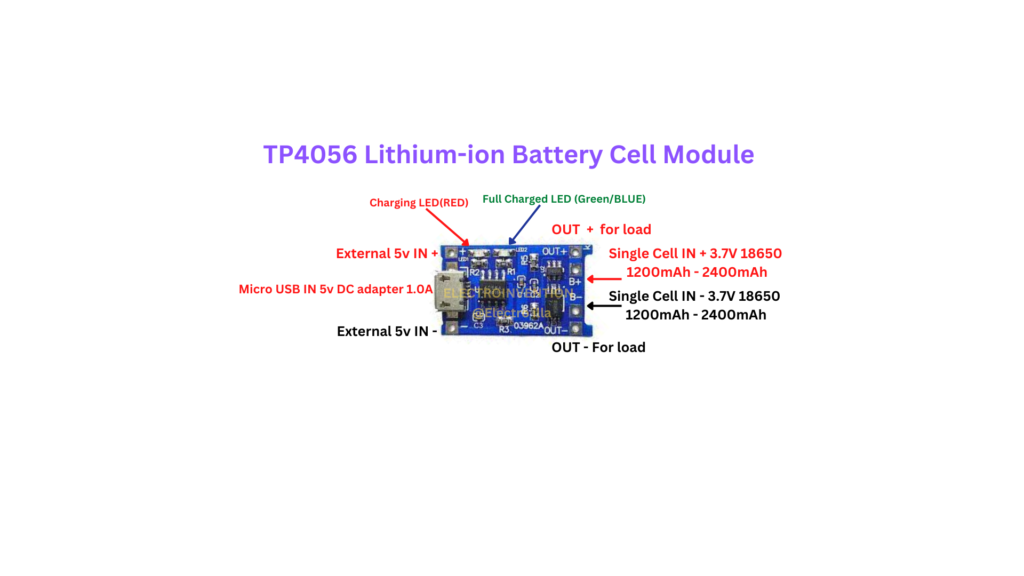
The BMS/Charger Module we will use is TP4056 single lithium-ion cell charger module.
TP4056 Single Lithium Ion Battery Charger Module?
TP4056 charging module is a Constant Voltage (CV) & Constant Current (CC) single 18650 3.7v lithium-ion battery charger module with Over Charging/Discharging protection, short-circuit protection, current and voltage monitoring, etc.
This Module Can be used with a 5V USB Wall Adapter (Micro or Type-C USB) to charge a Single-cell 18650 lithium-ion battery or with an external 5v power supply. This Charging module consists of a TP4056 Battery charging chip with some external passive components on board
Pinouts of TP40546 Charging Module
TP4056 18650 Single Cell 3.7v Charging Module Basic Features & Parameters
- Input Supply 4.5V – 6.0V
- Input Supply Current 1.5A
- Constant Charging Voltage 4.2V
- Full Charge Cut-off Voltage 4.2V ±1.5%
- Constant Charging Current Adjustable 130mA To 1A max with Re-prog Resistor (R3=1.2kΩ – 1000mA)
- Charging Indicator LED RED
- Full Charging Indicator LED BLUE/GREEN
- Max Power 4.2W
- Operating Temperature -10°C To +80°C
- Charging method Linear Charging
- Input Charging Interface USB (Micro USB OR Type-C) & Input Pins (Across the side of the USB port)
- Automatic Recharging
- Discharge Cut-OFF Threshold Voltage 2.9V
- Overcurrent Protection Threshold 3A (Sudden jump to >3A is considered as Short-circuit)
Note:- Other and better versions of the TP4056 module are also available in the market.
Material and Components
Proper Circuit Board Design plays a key role in arranging these components efficiently for stable charging performance.
- TP4056 Single-cell lithium-ion battery charging module
- LM7805 Linear Voltage Regulator
- AMS1117 Linear Voltage Regulator -SMT package
- IRFZ44n MOSFET
- 1KΩ Resistor -2pcs
- 220Ω Resistor
- 470Ω Resistor
- 1N4007 Diode -3pcs
- 100uf Capacitor -2pcs
- 1000uf Capacitor
- 470uf Capacitor
- 100nf Capacitor -3pcs
- LED-Green Colour
- LED-Red Colour
- 2pin-Terminal Block
- DC jack
- 12V SPDT Relay
- Blank PCB Board (8.0 cm x 7.5 cm)
- 2 Heatsinks
- 12V DC power supply/Wall Adapter -2A (Could be a 12V DC Adapter or a Solar Panel)
Circuit Diagram – Lithium Ion Battery Charger

Smart BMS Circuit Working – Lithium Ion Battery Charger
The circuit is pretty simple and efficient with respect to cost and complexity.
Operating the Circuit on the USB Supply
Suppose we charge the Battery with a 5V USB Adapter via the USB port on the TP4056 module. In that case, The TP4056 Module will directly handle the charging process with Constant current and Constant voltage while indicating charging with a Red LED – ON.
TP4056 will cut off the charging when the battery reaches a voltage level of 4.2V and the Green/Blue LED turns ON instead of Red LED indicating Full-Battery.
TP4056 provides the Battery output with all the protection (mentioned above in the specifications) from its OUT+ & OUT- Pins connected with the output filter capacitor and the Output Indicator LED-GREEN with a current limiting resistor (R4 = 220Ω) and the Output terminal header.
Operating the Circuit on12V DC Power Supply
In the case of using a 12V DC power supply (Solar panel or a wall adapter) with the circuit to charge the battery, The Red LED indicates a supply at the input through the DC jack, The battery will charge through the TP4056 charging module same as before but instead of getting power from the USB port.
The Charging module will get power from Input pins (IN+ & IN-) through the irfZ44N MOSFET (D2 used to prevent reverse current).
While the battery is charging in this case if the output is connected with some load the battery charging won’t get interrupted because the Output of TP4056 automatically gets isolated from the output through the 12v Relay at the output section.
The relay switches the output from the output PIN of TP4056 (OUT+) to the output pin of the AMS1117 Voltage Regulator and gives the output of the AMS1117 voltage regulator in the Output Section.
Here is how that works, The 12V gets filtered through filter capacitors at the input (D1 used for reverse polarity protection), The 12V relay will power ON (D3 used as Flyback diode), And Switches The Output as prescribed above.
The LM7805 Voltage Regulator converts the 12V to Slightly higher than 5V. This is because Resistor R1(1kΩ) is used instead of connecting the GND/ADJ pin of the LM7805 voltage regulator directly to the Ground, to drive the Gate of the MOSFET connected through a current limiting resistor (R2 = 1kΩ) with the LM7805 (LM317 Can be used here in place of LM7805).
IRFZ44N MOSFET is used to give a higher current capacity to Charge the battery through TP4056 charging module Input pins (IN+ & IN-), and the AMS1117 voltage regulator, supply indicator LED-RED with a current limiting resistor (R3 = 470Ω) is also connected with the output of LM7805 to give the output as prescribed above.
The main reason for using resistor R1 at the GDND/ADJ pin of the LM7805voltage regulator is that the irfZ44N MOSFET has a minimum Gate threshold voltage of 4V & also has some voltage drop across its Drain to Source path approx 0.6v so if the AMS1117 voltage regulator also draws power from LM7805 the output of LM7805 may drop below 5V including Indicator LED & other power losses, The MOSFET may not be able to give stable 5v output to TP4056 charging module.
Why not give 12V input directly to the AMS1117 voltage regulator you may ask? The reason is the AMS1117 voltage regulator has a max input voltage rating of 12V, but the optimal input voltage for the AMS1117 Voltage regulator is around 8V after that it may dissipate a lot of heat or may get burned.
Now after getting 5V 2A from the MOSFET the TP4056 module will charge the 18650 3.7v lithium-ion battery with constant voltage & constant current, tp4056 will indicate battery charging with inbuild Red LED and cut off the charging at 4.2v indicating Green/Blue LED. The load at the output will get supplied from the AMS1117 Voltage regulator until the 12v Supply(12v adapter/solar panel) is connected.
When the 12V supply disconnects the relay switches back to the Normally Connected(NC) and the Output load will not get supplied from the Output pin of the AMS1117 voltage regulator, Now the TP4056 will provide output with Short-circuit protection, over-discharge protection, etc (prescribed in specifications).
Make sure to use good heatsinks with the LM7805 Voltage regulator and irfZ44n MOSFET to cool them down while charging the 18650 lithium-ion battery.
To see the project working and more details, please follow the video below.
Working Video
If you guys like our content, then please do comment below. Subscribe to our Newsletter, it’s free!
Share it on Pinterest, Facebook, and other social media to show support. Thank You.