
We have already discussed many circuits to remote control home appliances. But they’re Infrared controlled and have many limitations. Today, in this article, we will be discussing how to use a cheap single-channel RC toy car’s RF module to remote control home appliances. We are also are going to discuss how to control 2 AC devices separately and even simultaneously using a single channel RF transmitter and receiver. And a video at the end.
In this, we have not bought any RF modules and have just utilized a single channel cheap remote control module taken apart from a China remote control car.
So, basically, we have 1 remote with two push buttons to make the motor move back and forth by changing output polarity on the receiver side.
The main problem with these cheap circuits is, of course, only one 1-channel and moreover, there are only push buttons to send signals. That means on the receiver side, a particular dc load is ‘ON’ (HIGH) until the button on the remote side is kept pressed. We have figured this out below pretty easily and with minimal components.
So below, in this article, we will see how to control 2 AC appliances with that single channel remote control module and overcome all its limitations. So, let’s get started.🤘🏻
Materials and Components
- IC CD 4017- 2pcs
- 1-Channel RF Remote Control Set
- 12V Relay- 2pcs
- D1,D2- LED-RED Color -2pcs
- D3,D4 1N4007
- R1,R2- 1K Ohm
- R3,R4- 100R
- R5,R6- 100K
- Q1,Q2 2N3904
- PCB , WIRES, JUMPERS,TERMINAL CONNECTOR
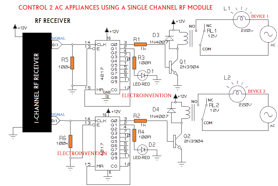
Circuit diagram to Remote control Home appliances
Working the circuit above to remote control home applicaes
The circuit is pretty simple and efficient with respect to cost and complexity.
A single channel RF remote control circuit from a cheap RC toy car is used which is having 2 push buttons at the transmitter side to make the car move back and forth. Receiver’s side: It can handle only handle one dc load i.t the motor, and changes the direction by reversing the polarity as per signals from the transmitter.
This reversing of polarity what we have took the advantage of, and are able to handle two loads at a time or separately.
Another problem was, the output from the receiver is just 5v-9v and it can only stay HIGH until the button at the transmitter’s side is kept pressed. We need a latch to stay open or Ground.
For this, we have used IC 4017 which is a sequential decade counter IC also a latch that is having 10 outputs, namely Q0 to Q9. There are internal select lines that increment the counter and select output lines whenever a clock input is received at its PIN number 14(CLK).
Now each wire of the receiver output is connected to separate 2 ICs Clock Pin(PIN 14). Whenever we press any one of the buttons on the receiver’s side, one of the wires is +ve and one is -ve. Vice-versa when another button is pressed. Every time a button is pressed, one of the wires is +ve and another one is ground.
According to each button, a particular wire is got +ve. That’s what we are required to trigger one of the IC. That’s what we needed.
Now we have two channels after this. That can allow us to drive two AC loads according to the logic given below in the Table.
The Working Conditions required to control the two Appliances
| Device 1(control by IC1) | Device 2(Control by IC2) | If we need? |
| 0 | 0 | Both devices OFF |
| 0 | 1 | Device 1 OFF, Device 2 ON |
| 1 | 0 | Device 1 ON, Device 2 OFF |
| 1 | 1 | Device 1 ON, Device 2 ON |
For understanding how it goes further, you need to understand first how IC 4017 is used and what different PINs work.
You can learn that here IC 4017 IR remote. If it’s already clear to you, then we can see that Q0 of both the ICs are connected to a separate NPN transistor that triggers the relay connected to it. When you power the circuit ON, by default Q0 of both the ICs are HIGH and the output goes to the transistor that triggers relays and the devices are getting AC supply.
Whenever a particular button is pressed and a particular wire out of two goes HIGH(positive), the IC’s PIN 14 connected to it.
The counter of that prticular IC is incremented and Output Select is now sequntially the next output line, “Q1”. Hence the transistor is also not getting any supply to it’s base.Resulting in relay being turned OFF.
Q1 is connected to the anode of a RED-LED(it’s your choice to use an LED or not) that glows indicating that now the device is OFF.
This way we can turn ON and OFF any of the devices and even we can keep both the devices Turned ON or OFF at the same time or separately. No matter you have kept the button pressed or released it.
This simple concept is helping us to make a 1 channel RF remote control to control two AC appliances.
Video
Thanks for reading if you still have any queries, you can comment below. Also do watch that video, subscribe to our newsletter. Do check this out: KnowledgeHub- Discussion
Recommended: DC 12v 2CH Channel Wireless RF Remote Control Switch Transmitter Receiver 10A Relay
I’ve seen some hairy arsed projects from “certain countries”. But wiring 240VAC through a solderless breadboard takes the prize.
Hello Dave, thanks for visiting.
Well, you have a point but will not exist till long. If you know the stuff you’re doing, you do it right. There is no harm in wiring AC through the breadboard if you know the basics of electricity and how to use that stuff with caution. There are over millions of videos on youtube doing that. This is the real-world and practical world. Bread board is safe and unless you don’t overload it.
This is great way to make things reuse for cheaper
Khub bhalo khub bhalo 🔥🔥🔥
Hello Nk, thanks for visiting and Glad you like it.