
Hello Guys. Hope we are doing very well. Already, I have explained some inverter circuits earlier on this website. From transistor-based to IC-based. Today, I am going to discuss another simple 100watt inverter circuit. I know already there are a lot of circuits over the internet and here too. I am going to add some more to them and give you some good circuit diagram and explanation. This simple100watt inverter circuit is just a square design and works well for the normal usage and travel bases. So, Let’s begin with our topic IC555 100watt inverter circuit, or we can say Simple 100watt inverter circuit using IC555.
IC555 Simple 100watt Inverter Circuit Diagram
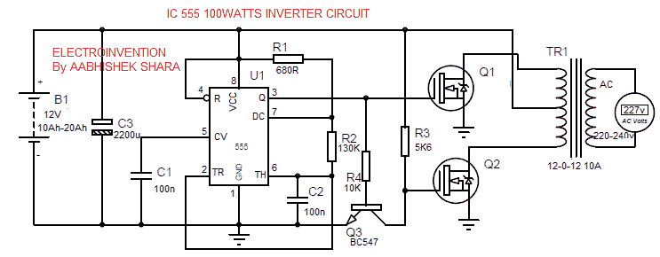
Materials and Components
- IC 555
- C1, C2 100n
- C3 2200uf
- R1 0.680 ohms
- R2 130K
- R3 5R6(5.6K ohms)
- R4 10K
- Q1, Q2 IRF540N
- Q3 BC547
- 12V 10Ah – 20Ah Lead Acid battery you can check the price for 12ah exide and buy.
- Transformer 12-0-12 10Amp
- PCB 1standard size
- Heatsinks 2 ( Separate standard sized for each MOSFET) Heatsinks 5 pcs @$ 1.18
- Tools like DMM(Digital multimeter, Soldering Iron)
Working and Design
I have already posted an article upon How do the inverters work? Design & Configuration. You can read that first to understand the working of an inverter.
The inverter circuit above is a square-wave based design suitable for travel bases or normal less sophisticated devices yet better than the one using transistor AMV. In the circuit above, the IC555 is set in an astable oscillator configuration to produce 55 Hz frequency according to the diagram.
The circuit’s components like R1, R2, and C2 are set accordingly to produce 55 Hz frequency with a 50.12% of Duty Cycle.
The frequency can be set and calculated by the formula below
F= 1.44/((R1+2R2)*C)
You can use an Online IC555 Calculator tool by Electroinvention to calculate and set the Frequency, Duty Cycle, time period as well as other factors and components. Just go on that Online IC 555 astable Calculator by the hyperlink above and you just need to fill three values and with just one click, you’ll have all calculations. This is a very helpful tool.
Astable means it has no specifically stable states and the output is in a periodic alternating pulse that oscillates between the VCC and -ve(0). This means high-low periodically with a frequency.
The IC555 is set in astable oscillator configuration and frequency is set to 55 Hz and a 50.12% Duty Cycle. A square wave AC output is taken by Pin 3.
The output from PIN3 is taken and fed to the gate of Q1 and also to the base of BC547. Both Q1 and Q2 are to amplify the low power signal to a higher power to drive the transformer and the load too.
During a positive cycle from the PIN3, one of its outputs is connected to the Q1 and the other one to the Bc547 transistor’s base. So, now the MOSFET Q1 is amplifying the signal and driving the transformer during time high. Also, this time the BC547 is ON and connecting the Q2’s gate to the ground junction.
During the negative cycle or the T0 or time low, output from PIN3 is absent. This time, via R3, the Q2 MOSFET would be turned ON and the terminal is again changed to drive the transformer (like ac). The whole of this process control via BC547 ensures the proper oscillation of the output signal. As well as, the proper driving and switching of stages.
This ensure the proper oscillations and cutoff and on driving and switching.
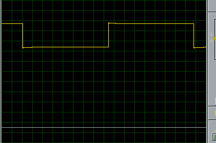
Below is the output waveform from the IC pin3
Backup Time , Power and Load
Using a 12v 10ah battery can provide a Total available backup power of 120watts. Similarly, a 12-0-12 10Amp transformer has a load handling capacity of max. rated up to 120watts.
So, if you are running a 100w Load with a 12v 10ah battery and same transformer, certainly you’ll get 1-hour backup and nit more than that.
BACKUP TIME =
- Backup time depends upon Battery ah value as,
- Total battery backup power(Ah*V=Wh) /power requirement by load per hour = backup time(in hours)
POWER OUTPUT=
- The Output power is dependent over MOSFETs used for each stage, Max rated transformer power V*A, and of course battery power backup.
- The Power you input, is the approx. the power you get as the output, not more than that. Efficiency depends upon the power factor also.
So Guys If you feel like to ask anything, you can comment it below and ask me. I hope you liked it Thank you.
Why we use IC555 in this circuit? What merits it give to us unlike other IC? The main concept of this circuit?
The main concept of working is already explained, the circuit is just for hobby projects, understanding, and practice with fun. IC 555 is used here so as to explain one more way to achieve it.
OK , from the circuit and its explanation, will the quantity of current flow when pin 3 is high across the transformer be thesame when the pin 3 is low across the transformer since R3 is connected to path along Q2
Yes, If you got a proper understanding of how this is working then you can see when IC PIN 3 is low, then the Q2 is Switched(Turned on and Q1 off) by R3. The current will be the same, just a slight difference will be there. No worries that are alright. And will work well.
This is one of the best site ever in electronics, Your site is very helpful, I have more questions, (1)how can we introduce a feedback in this circuit, if we introduce a feedback, what will be the advantage of the feedback with respect to when it has not been introduced in the circuit, (2)how can we achieve high power output like 500 or 1000w inverter using this circuit. (3) please upload a concept of pulse width modulation and its working principle with inverter ,
Hello Stanley, I am glad you liked my site this much. Thank you. For feedback design to be introduced, i.e which will not let output voltage to go down and will correct the output voltage as well, this is also called as output voltage correction to maintain the stability in the output voltage of an inverter. You can refer to this circuit https://homemade-circuits.com/wp-content/uploads/2013/10/inverter-output-voltage-correction-circuit-2.png .
To achieve higher Power Like 500w, you need to use a battery up to 12v 50 ah that will give you 600w power backup or 12v 100ah that will give you a backup of 1200wh approx. that can supply 500watts for up to 2 hours approx. In addition to that, you have to use at least 3*IRF540 MOSFETS in parallel both sides.
Also, you need to increase R3 wattage i.e 5K6 0.5w to 2 watts(first try 1watt if it’s fine) and most important use 12-0-12 50Amps Transformer which is capable of as much as 600watt theoretically but practically 550w(safe) of power output.
Use separate heat sinks for both sides MOSFETs, Like, 1 big heat sink for drains(common) of 3 MOSFETs of 1 side and 2nd big heatsink for another side 3 MOSFET’s.
I have tried to explain to you in very easy language as much I could. I hope you got it. First, try to build a smaller power inverter then move on to high power. Also, replace BC547 with TIP122.
Use good quality heatsinks of large size, Good Quality of MOSFETs, Good quality of transformer, never exceed the rated Load, Use Good battery as suggested, Do not do any mistake.500Watts isn’t safe if anything you did wrong. Be smart be safe best of luck.
Keep in touch.
Use good quality Heatsinks , MOSFETs,
OK. I have understood it. Thank you so much,
Thanks a lot sir, please my question is, how does a two MOSFET switches the inverter to make it an Ac source since both tapped from one point, pin 3 of the IC, I mean how does the two MOSFET works starting from the 555 timer ic output when considering each circle of the waveform,
Hello Stanley, Thanks for visiting. The work of oscillations is being done by the IC555 Astable oscillator, to generate pulses according to specific frequency that is set by components. Both the MOSFETs aren’t turned connected to the PIN3, also, Both aren’t turned ON at the same time. They are switching between.
During a positive(high) cycle from the PIN3, one of its outputs is connected to the Q1 and the other one to the Bc547 transistor’s base. So, now the MOSFET Q1 is amplifying the signal and driving the transformer during time high. Also, this time the BC547 is ON and connecting the Q2’s gate to the ground junction.
During the negative cycle or the T0 or time low, output from PIN3 is absent. This time, via R3, the Q2 MOSFET is turned ON and the terminal is again changed to drive the transformer (like ac). The whole of this process control via BC547 ensures the proper oscillation of the output signal. As well as, the proper driving and switching of stages.
I hope your doubts are cleared. This how it works. If anything isn’t clear, then please read the working paragraphs again.
Thanks for visiting.