
Hello Engineers. Hope you all are doing good. At places like kitchens, commercial kitchens, Fireworks factories or welding shops, etc places a proper exhaust system is required. An automatic exhaust system will be much helpful at these kinds of places. So that anyone if forgot to open the exhaust system, then too this automatic exhaust system circuit automatically detects the gases and smoke. And the exhaust system is automatically started. I have used MQ-2 gas sensor module for sensing. MQ-2 itself is capable of sensing LPG, i-butane, propane, methane and smoke. Wide detection range,isn,t it? So, let’s get started with our topic Smart automatic exhaust system circuit or automatic exhaust fan controller / smart chimney.
To get more understanding about MQ2 working and structure click the hyperlink in above paragraph.
What is an automatic exhaust system or Smart smoke exhaust system?
An automatic exhaust system or Auto exhaust fan controller is a system circuitry which is having a series of some sensors and electronics components to detect and exhaust various gases and smoke. This type of circuitry uses some specific gas and smoke sensor to detect the specific gases or smoke and then turn on the exhaust system automatically.
Basically most of these are using MQ-2 gas sensors that has a wide detection range like LPG, i-butane, methane, propane, alcohol and smoke. With this variety of detection it can be employed any where in places such as kitchens, industries, welding shops and commercial kitchens,etc.
For Welding shops MQ-7 and MQ9 are much better for welding as they are specified to detect carbon monoxide.
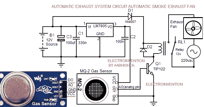
Circuit Diagram for For Automatic Smoke Exhaust system
Materials
- MQ-2 sensor( buy from amazon at @ $2.91 each) – 1pc
- Q1 TIP122 – 1pc
- 12v Battery or any 12v 2A source
- C1 330nf – 1pc
- C2 100nf – 1pc
- C3 100uf – 1pc
- LM 7805 – 1pc
- Relay 12v – 1pc
- D1, D2 1N4007 – 2pcs
- PCB 1pc
WORKING
Above are the circuit diagram and the components required mentioned. The circuit employs an MQ-2 sensor as the main sensing unit. MQ-2 sensor due to it’s wide option of detection capability is suitable for most of the places. The sensor unit can be installed above the work bench place or main work area so that it easily senses and can automatically turn ON the exhaust fan.
A 12V battery or power source is powering the whole circuitry. So, here the MQ-2 sensor when detects smoke or gases like LPG, butane, propane, etc. Gives out a T-TL output signal to the transistor Q1’s base. Now, Q1 gets turns ON after getting its base Biased. The transistor Q1 ( TIP 122) then turns ON the relay by connecting its coil’s another end to ground. The relay’s COM Pin is connected to the 220v AC source and NO is connected to the AC exhaust fan system.
After getting turned ON, the COM PIN’s connection shifts from NC to NO. This now connects the exhaust Fan to the 220 v AC source. Now the exhaust fan is turned ON till the sensor is sensing the specified gas, smoke.
If the smokes or gases are stopped or not being sensed by the sensor, then it stops giving output to the Q1. And hence, the relay is then OFF making the com pin connected back to the NC( normally connected) PIN.
So, this same process is carried ON till the work is going ON. You can use any 12v power source, whether it’s a 12v battery or 12v DC adapter. If you are using a 12v DC battery then make sure its minimum above 1.6 ah. But if you use a 12v battery as the power source, then you have to provde a provision to charge it too.
I prefer use a 12v DC adapter whose current output should not be lesser than 1A, if it’s 2A, then that would be fantastic.
Install the sensor in such a position so that it can easily detect and sense the gases as well as smokes or fumes. For detailed working principle and types of gas sensors read this article about gas detectors from wikipedia.This was all about this circuit design idea. Hope you liked it and the and concept is clear.
This was all about this automatic exhaust system.
great Job. good project
Hello Bruno, thanks for visiting. Glad you liked it.
Thanks
Awesome design but I have have a question can it be installed inside the factories (i mean in the vast open surroundings ,because the chances of catching fire is more in factories ) if yes then tell me how this can be done. I like the concept more then design:)
Hello Rishi, Thank for visiting and glad you like it. yes, it can be, but for that, it needed to be set up on large scale,m multiple sensors, and High power relay, also the circuit will have to be modified.
BTW congratulatulation brother for this website
How can I combine it with a chimney in my kitchen to make it automaitc?
Hello Hajis, You can use either this circuit or if you want to automate your chimney, then you can make the circuit the same but instead of connecting fan after the relay, you have to connect the chimney wire and AC supply.
nice design
Thanks for visiting.
Well done
Hello Sulaiman, Thanks for visiting.