
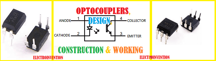
Hello Engineers. In this tutorial, we are going to discuss optocoupler. An optocoupler is a semiconductor electronic component that is used to link two separate electrically isolated circuits using a light-sensitive using light-sensitive means.
An optocoupler is somewhat similar to a transformer. Although it does not work in the direction to step up or down the voltage, but provide electrical isolation between two separate circuits.
To be more clear, in a transformer, the two coils, primary and secondary are electrically isolated but still, the output at the secondary coil is linked to the supply at the primary coil. The two coils are isolated but linked via electromagnetics and inductance.
Similarly, in an optoisolator/ coupler, the two separated circuits are coupled together through a link by a light-sensitive interface. Whenever we need to provide isolation between an input signal to turn another output circuit ‘ON’ via a light-sensitive path we use optocouplers, which are much more efficient and cheap.
This is why optocouplers are also known as optoisolators or photocouplers.
The basic design or architecture of an optocoupler involves an IR emitter LED and an infrared sensing element that can be an IR diode, or phototransistor, or a photo SCR(photo silicon controlled rectifier), or a photo TRIAC. In order to sense that emitted light and open the pathway or to turn ON the circuit connected with its another end.
A basic design for a Phototransistor optocoupler can be understood by the figure below.
Phototransistor Optocoupler : 4N35N/4N25N
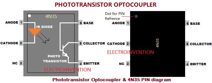
Here is a phototransistor optocoupler is shown in the figures along with commonly used 4N35N phototransistor optocoupler IC pins. The input signal from the first circuit is applied at the input of IR LED, which in turn, emits the infrared light onto the phototransistor. This light’s intensity is proportional to the strength of the input current. And the intensity of this light also affects the conductivity through the phototransistor.
This makes the transistor turn ON and now that transistor starts behaving like a normal BJT transistor.
Now, the transistor is like a normal switch. This is how one circuit can here control another one with having electrically connected to each other.
Below is a simple circuit with a phototransistor optocoupler IC (4N35) to be used in a simple configuration to drive a load.
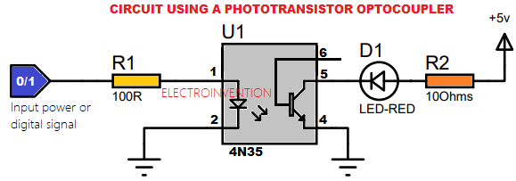
The above circuit is using a 4N35 optocoupler IC to be used as a phototransistor optocoupler. An input signal is applied at PIN 1, it may be a power input or a data signal from a microcontroller or any ICs, which can be 0(LOW) or 1(HIGH).
When the input is High, the IR LED emits the infrared light with an intensity proportional to the strength of the input signal. This makes the phototransistor turn ON and now behave like a normal switch.
The Amount of current conduction by the phototransistor is controlled by the amount of IR light emitted by the LED.
Now at the load side, we have PIN 5, a collector of transistors connected to the R2, then to the load ED’s cathode. The anode of load LED(D1) is connected to the positive of another power supply.
The Pin 4 is emitter and it is connected to the ground. PIN6 is the base, but you can use it to control the switching sensitivity of the photocoupler(using a resistor to the ground) or leave it unconnected. PIN 3 is not mentioned above and is NC, it will be NOT CONNECTED.
A phototransistor optocoupler is the most commonly used optocoupler and can drive even heavier loads, like a power transistor, relay, or a particular power stage or controller circuit.
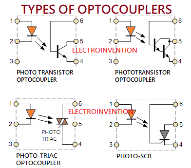
Types of optocouplers
Basically, there are 4 types of optocouplers usually used.
- Phototransistor optocouplers
- Photo-darlington pair optocouplers -just use transistor pairs as darlington pair to drive more heavy loads.
- Photo-SCR(Silicon controlled Rectifier)
- Photo-TRIAC
Phototransistor and Photo-darlington optocouplers are usually not NPN transistors based and photodarlington uses darlington pair instead of one transistor.
They are mostly used to drive DC loads like a relay, Transistors, or other DC circuits.
Photo TRIAC and Photo SCR can be used to control AC Loads.
We have already discussed about phototransistor optocouplers with an example of 6 PIN optocoupler IC 4N35. Let us also discuss one more, most commonly used 4 pins Phototransistor optocoupler IC, PC817.
Phototransistor optocoupler: PC817
The above circuit is also using a phototransistor optocoupler. This one is using PC817 which is a 4 PIN optocoupler IC. It is a commonly used optocoupler. Working is the same just as how a phototransistor optocoupler should work. PC817 just provides single isolation at one time.
Photo-TRIAC optoisolator
Photo-TRIAC optocoupler, also called TRIAC Optocoupler is a kind of optocoupler that is similar to other types but instead of having transistors, it has a photo-triac installed inside its packaging.
Usually, TRIACs(Triode Alternating Current) are used to handle AC loads and higher power devices like TRIACS, MOSFETS, High power Loads. One of the most common types of photo-TRIAC optocoupler used is the 6PIN MOC3021. We will be taking it as an example to understand in detail.
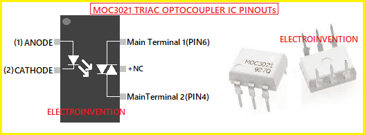
The Peak output voltage at its TRIAC side is max. 400 volts and Max. The output voltage is 280Volts AC. With a current of 1 ampere. To drive low voltage high current devices we must interface it with some other TRIAC or amplification component like a power transistor or a circuit as shown in the circuit below.
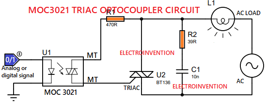
The above circuit shows how to use MOC3021 optocoupler IC to control AC loads. The overall working is the same as any other optocoupler IC, just the only difference is that here we have photo-TRIAC instead of an NPN transistor.
I hope you guys liked it. Tell us in the comments below if you have any questions or a suggestion.
It’s very helpful for electronics begginers I like it
Really Very Helpful
Hello tushar, thanks for visiting and glad you liekd it