
Hello Engineers. Hope all are well. Security and automation are a great demand in this era. In this article, I am going to discuss a Number locking system based door lock. This is a cheap and effective way for low level based security by using number locking system based door lock protection. Security is required everywhere, be it home, office, banks, Locker Room, Safe, etc. And, different kinds of security systems are used depending upon the degree of protection and complexity of security measures required. The number locking system based lock circuit to be discussed in this article is good for normal level security using a number lock or key PIN lock.
Based on the required complexity and difficulty level required, the circuit can be modified accordingly, with more number of digits key PIN. The circuit shown here is having 4 digit key pin, each button represents a particular digit and the rest are wrong buttons that will just reset the IC counter. All the buttons are jumbled and the lock system will be having a fixed password key depending upon the circuit’s physical configuration between IC and buttons.
Let’s dive more deeper into the real concepts…
Counter and Controller part : IC CD 4017
We have here used the IC CD 4017 here as the main controller for this device. IC 4017, as we know is a 16 pin CMOS decade counter IC, with fic decoded output pins. It has the capability to turn on 10 different outputs sequentially, each time a clock pulse is received with the desired set time and reset. We have here took advantage of this counter. To get the input clock pulse to run the IC counter through the user, but a set of 8 pushbuttons.
Out of the 4 are correct and rest 4 buttons and are just wrong to confuse the key combination and if pressed, then it will reset the counter by giving logic 1 to the reset pin.
Let’s discuss further with circuit diagram, materials required and circuit working.
MATERIALS
- IC 4017
- Pushbuttons – 9 Pcs
- R1,R3 100K – 2 pcs
- D1-D5 1N4001 – 5 pcs
- Relay 12V
- 16 Pin DIP connector(to mount the IC on it)
- Q1 BC547
- 12V Solenoid Lock at a very cheap price.
- PCB
- 12v Power source ( 2 separate, 1 for the circuit and one for the solenoid lock) at least 2A
Number Locking system based door lock Circuit Diagram
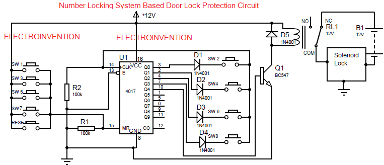
As stated above, in the circuit we have used IC4017 as a controller. The IC is a decade counter that can turn on 10 outputs from Q0 to Q9 sequentially. The counter increments to 1 whenever a clock pulse is received at the pin 13 of the IC.
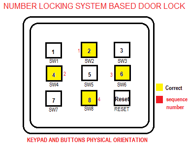
The input clock pulse is here taken from the user itself, through some 9 push button switches. Out of which, 4 switches are of right combination of the key pin and rest 4 are wrong to confuse the user and reset the the counter. 9th switch is RESET button.
The input buttons SW 2, SW4, SW6, SW8 are the right combinations to be pressed and increment the counter and turn on the door lock. Whereas, the other switches SW1, SW3, SW5, SW7 are just to reset the combination and also to increase the complexity.
Circuit Working
The Circuit is powered by 12V DC input. PIN 16 of the IC takes the VCC input and Pin 8 (GND) goes to the ground. The switches from SW1, SW3, SW5, SW7 are the wrong buttons. One side of these switches are connected to the battery positive and the other side is connected to the Pin 15 (MR) of the IC. This is the memory reset pin of the IC when this pin goes high, the counter is reset and the combination entered by the user is also reset.
The pin 15 is also connected to R1, which keeps the Reset pin connected to the ground, it can also be called a pull-down resistor. Whenever a button amongst SW1,3,5 or 7 the reset pin gets +ve input and once it goes high, it resets the counter again to Q0.
When the IC is given power, at first, its output is on Q0, i.e pin 2. We have the correct password sequence followed by the switches, SW2→SW4→SW6→SW8. One side of these buttons is connected to 4 output pins of the IC (from Q0-Q3) and the other ends are connected to each other and common ones go to the PIN 14(CLK) of IC. It is also necessary to press all switches in the same sequential manner.
When SW2 is pressed, the output from pin 3 is shorted to the CLK pin if the IC. After the clock pin gets a pulse, it increments the counter to 1, and now pins 2(Q1) is high, so now the user should press SW4 to increment the counter as the output of Q1 triggers the clock pin again to increment the counter. And this goes on until the SW8 connected to pin 7(Q3 output line) is pressed. Now this time when the clock pin gets a trigger and the counter is incremented, PIN 10 gives output to the base of the BC547 transistor. After the transistor is turned on, it turns on the relay and now 12v solenoid lock stops getting the supply and the door is unlocked.
If any button of wrong combination(sw1, sw3, sw5, sw7) is pressed in between the correct password buttons, then that will reset the counter again to Q0.
When you have to reset the entered key or you have to turn on the lock again, then just press the RESET button. Doing that will again reset the counter and output again goes on Q0, and Q4 is now low, making it to turn off the transistor and relay setup. This makes the lock again getting supply 12v and the door is locked again.
Make sure you use separate power supplies for the circuit and solenoid lock. OR, use a diode 1N5400 and a good power supply of at least 12v 3A and add after the power supply to create a separate power source line for the solenoid lock.
great. i think i will work on this. its simple and components easy to find
Hello Bruno, thanks for visiting again. Yes, it’s very simple yet effective. You should give it a try.
Very nice design and explanations everything is awesome