
Hello Engineers, Whenever making motor-based projects using any microcontroller IC we need more power in order to operate the motor. This power, can not be provided by any of the microcontroller ICs as motor requires a lot of power than the microcontroller consumes. For this, we need to use a motor driver with a microcontroller(L293D motor driver ic used here). Motor drivers are found in almost all embedded systems applications requiring a motor. For eg.line follower robot, obstacle avoiding car, automatic security latch/door.etc.The work of the L293D motor driver IC is to take control signals from the microcontroller and provide the motor enough power to run according to the control signals.
So, today I am going to explain about L293D motor driver IC and how to interface it with a microcontroller. Starting with the introduction to L293D followed by its working, with a diagram, and its interfacing with microcontroller and dc motor. with an AVR code and a simulation video at last.
Introduction L293D
L293D is 16 pin motor driver IC used to interface DC motors with a microcontroller. It can be found in almost all motor-driven embedded systems projects. L293D is a motor driver that allows running a motor in both directions. It can control 2 DC motors simultaneously. It’s also an H-bridge motor driver IC.
This works on a concept of H-bridge, as you know voltage direction is needed to be changed in order to change the motor shaft rotation direction i.e clockwise or anti-clockwise so an H-bridge motor driver is a good fit. In one IC there are two H-bridge sections that control two DC motors bi-directional rotation. Below are the diagram and IC pinouts.
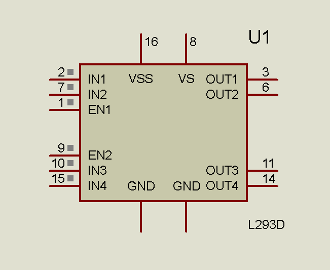
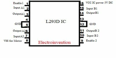
- So, above are the IC’s structural as well as diagrammatical pinouts markings that show 2 sides of IC L293D.
- On the left side of the IC’s face, pin#1 is the Enable1 which is given +5v to activate all pins on the left side.
- Below it, are the pin#2 & pin#3 which are Input1 and Output1.
- PIN 4 & 5 are the grounded pins.
- Pin#6 &7 are the Output2 and the Input 2.Pin #8 is VSS means supply voltage input for driving the DC motor.
- On the right side Pin 9 which is Enable2(+5vin) and activates all the I/O pins on the right side, the rest of the pins are I/O and GND(Ground)except the VCC which is the power input to turn ON the IC.
Input Pin’s logics (either 0 or 1) received from the microcontroller decides the rotation of the motor. i.e clockwise or anticlockwise. So, in all, PINS 2,7 and 10,15 are input pins that receive input from microcontroller i.e low or high.
Below is the Table showing input signals and their effects over the outputs. Let’s consider pin 2 and pin 7.
LOGIC TABLE
| INPUT | INPUT | OUTPUT |
| Pin2=1 | Pin7=0 | Clockwise rotation |
| Pin2=0 | Pin7=1 | Anticlockwise rotation |
| Pin2=0 | Pin7=0 | Idle{no rotation} |
| Pin2=1 | Pin7=1 | Idle{no rotation} |
Interfacing with the Microcontroller
Here I am using ATmega16 microcontroller IC (click on the link for basics of avr).L293D will receive control signals as logic 1 or 0 from the microcontroller and operates the motor accordingly. Below are a circuit diagram and a small AVR programming code to control the motor.
Circuit
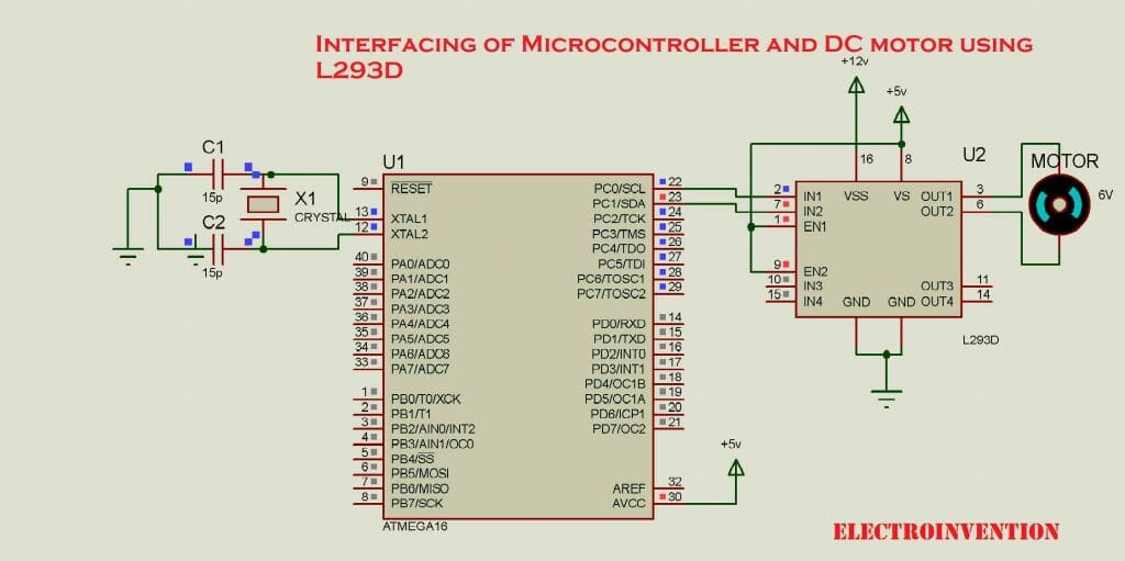
In the above circuit, I have connected PC0 of PORTC to the Pin2# of l293d and PC1 to the Pin7# of l293d. and output is from L293D’s Pin3 and pin6. So according to the above logic table If pin2 of the motor driver is at Logic 1 and pin7 is at Logic0 then, the motor’s rotation must be clockwise.
Similarly, when the pin2 is at logic 0 the output from Pin 3 will be 0(grounded) and pin7# at logic 1 input then pin6 output will be high. so the motor rotates anti-clockwise.
Below is a program code to interface L293D, microcontroller, and the motor to perform with some programmed functionalities. So let’s see the code first.
#include <avr/io.h>
#define F_CPU 8000000UL
#include <util/delay.h>
int main()
 {    DDRC=0XFF;
     while(1)
     {
         PORTC=0B00000001;
         _delay_ms(3000);
         PORTC=0B00000010;
         _delay_ms(3000);
}return 0;
}
In the above program, I have declared all pins of PORTC as output by DDRC=0XFF; Then, pin PC0 is given logic1 and PC1 set at logic0 and the same is going to pin2&3 input of L293D and motor rotates clockwise for a time of 3 seconds given by _delay_ms(3000);.
After 3 seconds time, the case is reversed as the logic output from the microcontroller is reversed by PORTC=0B00000010; by keeping Pin PC1 as high and pin PC0 as 0.See table to get more understanding and simulate this circuit and code yourself. Use AVR ATmega16 development board that would be easy to configure, program and use with L293D motor driver.
Below is a short video for simulation of the circuit and code working.
I hope you guys liked it. Please let me know in the comments. For any queries, you can ask me in the comments. For more interesting blogs, stay connected.
nice
Hi, Piyush thanks for visiting, stay tuned.