
Hi, guys hope everyone’s good. Christmas is coming and in this article, we are going to discuss a two-channel Christmas light circuit that can blink drive 30 LEDs in total. This Christmas Light circuit has two channels and is powerful enough to run15 normal 10-20mA LEDs per channel. This is usually like a flasher with a multi-channel and LED string blinking speed control option too.
The circuit is simple and powerful. This Christmas light circuit can even hold more than 15 normal LEDs per channel. Christmas 2020.
Each LED channel turn on and off one after the other in a simultaneous fashion just like a flip-flop or an array.
Materials
- IC 555 (of course with the DIP connector Base)
- Q1,Q2 IRF540N MOSFETs – 2pcs
- Q3 BC547 -1 pcs
- C1- 10nf – 1pcs
- C2 – 10uf – 1pc
- R1-10K
- VR1- 100K Pot – 1pc
- R2- 5K6 – 1pc
- R3- 10k -1pc
- R4-R11 – 100 to 220R -8pcs
- LEDs- 2 Colors- 15 to 20 pcs each color
- 9-12V power Supply 2Amp max.
- Misc. Wires, PCB Board Wire connectors,etc.
Chrismas Light Circuit 2-channels LED Flasher
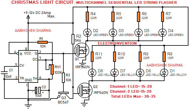
The circuit shown above is very easy to make and powerful as well as easy to use. The circuit is basically an LED Flasher with 2 multiple channels controlled by Q1 and Q2 Mosfets. Each channel can have 15-20 LEDs. The Blinking speed of this circuit can be varied with the help of RV1.
When Q1’s controlled channel is ON, Q2 is Off, and vice versa. This keeps going on sequentially.
Working
Now you know what the circuit is and what functionality it does. The circuit can be powered with any power source providing 9-12V DC @ 2Amps max. This much power is more than enough to drive those tiny 10 – 20mA 3V or LEDs.
The main control circuit is basically an LED flasher / LED blinker circuit. I have discussed 2 of them already on this website. Choose the one you find easy and suitable.
The Flasher timer circuit can be created by using an astable multivibrator circuit(You can do it by using IC555 or by transistors and capacitors combination).
I have used IC555 for this Astable timer circuit as it’s compact, versatile, and better than just using transistors. In case you want your own timer settings you can calculate the frequency, T1(Time high), T0(Time low) by using this IC555 Astable Oscillator Calculator Online.
Although, I have done it for you and you can follow this circuit and it will provide you Frequency for the flasher between 0.6 to 5Hz. Remember higher frequency means less you’ll see LED string blink. As the higher frequency means a higher number of times LED blink per second. Your eyes can’t catch that high-speed oscillation.
So, now we are done with the Astable timer part. Let’s move further to the channel distribution and driver stage.
As stated, this LED flasher has 2 channels. 1 is controlled by IRF540N at Q1 and the other one (channel-2)by IRF540N MOSFET which is labeled as Q2 in the circuit.
When IC’s PIN 3 goes high
The Q1 conducts and as the gate gets supply voltage, the channel gap reduces, and the LED string with Q1 turns ON. During PIN 3 of the IC is high, one more thing happens. The base of Q3 transistor BC547 also goes high for the duration. This makes sure that the Q2 keeps off and does not turn ON.
When the PIN3 of the IC goes low
Q1 is eventually off and Q3 too. This time Q2 is turned ON via R2 which is 5.6K ohms. This enables the Q2 to turn ON and get supply, enabling the LED string of channel-2 to turn ON.
This is how it works. The circuit is simple and powerful. Hope you guys enjoy Christmas.
If you liked it, try it. Also comment below. Thanks.
I do agree with all the ideas you have introduced to your post. They are very convincing and will certainly work. Still, the posts are too quick for novices. May you please extend them a little from subsequent time? Thank you for the post.
Great help man
fully explained, keep it up all the time.No questions neede to be ask
Hello Lugabihl, thanks for visiting and glad you liked it.
Ver cool thanks for this one
Cool
Ꮋi! I’m at work browsing your blοg frоm my new apple iphone!
Just wanted to say I love reading through youг blog and ⅼook forward to all your
posts! Keep up the fantastic work!
I love visiting this site
I learn alot from it
Hello, Thanks for visiting again and again. I am glad to hear that.
Pretty cool. And happy new year
Thanks for visiting and glad you liked it.
Khub bhalo
Hello, thanks for visiting and glad you like it
I want participate in this innovation
hello, thanks for visiting, glad you like it