

Hello Engineers. In this project, we will make a simple 1-watt audio amplifier circuit using lm386 opamp. You may be wondering just 1 Watt!! But trust me this 1 Watt power audio amplifier circuit is enough to rock on a whole small cabin or room. This is a low-power high-performance audio amplifier. It’s equivalent to your laptop’s speaker.
This circuit can power a 4ohm to 8ohm speaker.
Here are some specifications of the LM386 IC:
- Can be operated on 5 to 9V Battery
- Minimum number of External Parts
- Wide Supply Voltage Range: from 4 V–12 V or 5 V–18 V
- Low Quiescent Current Drain: 4 mA
- Voltage Gain ranging from 20 to 200
- Ground-Referenced Input
- Self-Centering Output Quiescent Voltage
- Low Distortion: 0.2% (AV = 20, VS = 6 V, RL = 8 Ω,
- PO = 125 mW, f = 1 kHz)
- It is available in 8-Pin DIP Package
Pinout of LM386 IC:
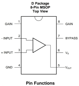
LM386 is an 8 pin IC the pin description are as follow
Gain: PIN 1 and 8 are the gain control pins that connect a capacitor in series with a resistor to control the gain of the opamp. The gain of the opamp can be varied from 20 to 200.
Power Supply: pin number 6 and 4 are the power supply pins. PIN 6 is +Vcc while 4 is ground. You can use a 9V battery source.
Bypass: pin number 7 is the bypass terminal, connect a 100 to 250uf capacitor at pin 7.
Input terminals: PIN 2 is the inverting and pin number 3 is the non-inverting input terminal of the opamp.
Output: pin number 5 is the output terminal.
Construction of Audio Amplifier circuit using LM386 OPAMP :
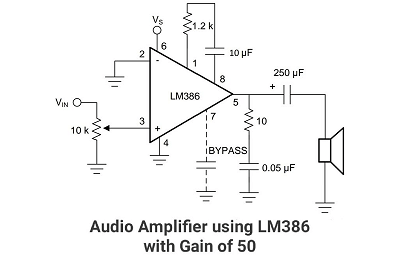
The circuit’s power supply Vs can be any normal 12v DC 500mA source or 9v 1A source.
PIN 2 and 4 are connected to the ground. Pin 3 is the non-inverting input terminal. You can take input from a microphone or a 3.5 mm audio jack. Use a 10k potentiometer to control the volume.
A bypass capacitor is connected to pin 7. To control the gain of the amplifier connect a potentiometer between pin 1 and 8.
Here we are setting the gain of the amplifier at 50 by connecting a 10uf capacitor in series with a 1.2k ohm resistor between pin 1 and 8.
The output of the opamp is given to a 4 to 8-ohm speaker via a coupling capacitor of 250uf capacitor. To remove the high-frequency noise connect a 0.05uf capacitor between output and ground.
Working of LM386 Audio Amplifier:
The lm386 is a versatile audio amplifier ic, it is specifically designed for audio frequency range. Its working is the same as the working of opamp.
It amplifies the difference between its two input terminals. As pin 2 is grounded it amplifies the input voltage with a gain of 50 and provides an output at the 5th pin.
The bypass and coupling capacitors are used to remove the noise components making the output more smooth and clean.
Applications of LM386 IC:
- AM-FM Radio Amplifiers
- Portable Tape Player Amplifiers
- Intercoms
- TV Sound Systems
- Line Drivers
- Ultrasonic Drivers
- Small Servo Drivers
- Power Converters
I hope You Guys Liked this. Also please comment below if you have any doubts. Thanks
Niceo
noice