
Hello Engineers. In this article, we’re going to talk about making a Piano using IC 555. This will be a simple and very well working mini piano using IC 555 and some other passive components like resistors, capacitors, etc.
Sound travels by the to & fro displacement of the particles of the medium. Sound waves are longitudinal waves by nature.
Sound waves are also called pressure waves as compression and rarefactions in the medium is generated due to the to and fro vibrations of particles.
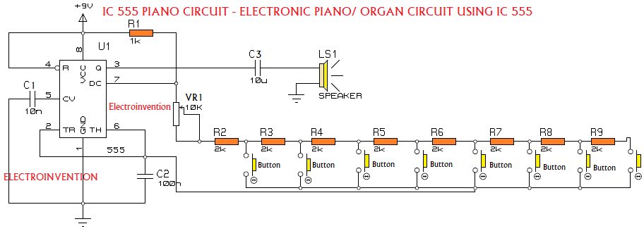
Here the frequency generated by the IC555 astable is converted to sound. There is an 8R(8 Ohms) speaker for the sound output. So, let’s begin with our electronic mini piano using ic 555.
Circuit for Piano using ic 555
Components
- IC555
- R1 1K ohm resistor
- R2-R9 2K ohms resistor
- C1-10nf
- C2 100nf(0.1uF)
- C3 10uF NPC (Non-Polarised Capacitor)
- LS1 Speaker 8R, 0.5watt Very Cheap, and good quality
- Push-Buttons 8 pcs
- PCB, 9v Battery, Battery connector
Working
The circuit for this mini electronic piano can be powered using a 9v battery. We already know that a speaker is a device used to convert electrical signals to a specific sound tone.
We also know that the sound tone is generated by the regular vibration at a specific frequency. Amplitude is dependent on the power and amplitude of that signal. To produce a sound, the diaphragm of the speaker vibrates according to the applied frequency and amplitude of electric signals.
Here we have used IC 555 in astable multivibrator configuration to generate frequencies audible by the human in the range of 20Hz to 20Khz. The signal from Pin 3 is hence then converted to a specific sound tune with certain intensity and frequency, we will discuss that below in detail.
We suggest everyone understand how an IC555 astable multivibrator works and how to calculate its frequency and configuration, click here.
It is easy to understand the circuit if you understand the basic working of IC555 and astable multi-vibrator.
Here the C2, R1 and resistors R2-R9 are all responsible determining the frequency of IC 555 operating in astable mode. You can get an idea from the below image and formula on how to calculate that.
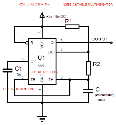
With the image above it can be clear how to calculate and select components to determine the frequency of this astable oscillator.
F(Frequency)= 1.44/((R1 + 2R2) * C).
NOTE:-R2 here refers to any resistor from R2-R9 in our piano circuit & C is C2. Click here for the IC555 Astable oscillator calculator Online Tool we have made to ease your work.
In our Piano circuit, the R1 and C are fixed values and R2 is selectable. (from R2-R9). Whenever a button is pressed, it selects a particular resistance value and also completes the circuit between PIN 6 and 7.
Remember the formula f=1.44/((R1 + 2R2) * C).
C1, 10nF capacitor is connected to PIN 5 of IC to avoid high-frequency noises/distortions, and the capacitor C3 (10μF) is an NPC used as a coupling capacitor to block dc and bypass ac signals to the speaker. (Remember capacitor blocks DC and Bypass AC? Have you read this earlier?).
The generated tone type can be changed by varying the VR1, 10K .
So, this is how our mini piano using IC555 works. I hope you guys have liked it. If you have any questions you can ask in the comments.
Make sure you join our Electroinvention’s new KnowledgeHub community.
Thank You.
Great man you
Very nice sir