
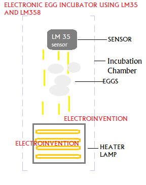
Hello Engineers. An Electronic egg incubator is an electronic device that is used to artificially hatch the eggs without the hens. An electronic egg incubator circuit creates an artificial environment and mimics the conditions required for hatching the eggs. These can be, temperature, humidity, and atmosphere.
Here in this article, we are going to discuss a very simple electronic egg incubator circuit using LM35 and LM358 OP-AMP, that allows maintaining the temperature suitable for the incubation of eggs and auto-ON-off the heater when temperature tries to go up and down.
Electronic Egg Incubator Circuit
- LM 358 IC
- LM 35 Buy here cheap&Trusted
- C1 22uF
- C2 330nF
- R1 27K(must be exact)
- R2 2K(must be exact)
- LM7805 Voltage regulator / Or any 5V 2Amp supply
- Relay 5V
- PCB
- Q1 2N222A or BC337 Transistor
- D1 1N4007
LM35 Temperature Sensor
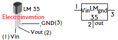
LM 35 is a precision IC which is an analog temperature sensor whose output voltage is linearly proportional to the temperature around it. LM 35 and LM35C are rated to operate over ℃ and operate in below temperature ranges:
LM35: −55°C to 150°C and LM35C: −40°C to 110°C range (−10° with improved accuracy).
Input voltage ranges from 4v- 30Volts, and the output voltage gain is 10mv per ℃.
Working
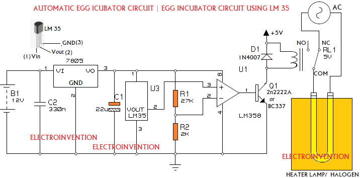
The circuit can be powered directly by a 5V 1-2Amp power supply, or use a 12V Supply with an LM7805 regulator.
I have used LM358 which is a dual op-amp IC. You can any one of the Op Amps available in the IC. Pins 1, 2, and 3 are associated with one op-amp and pins 5, 6, and 7 with the other. I have used the first op-amp i.e. pins 1 (OUTA), 2 (INA-), and 3 (INA+).
In this circuit, LM358 Op-Amp is configured as a comparator, that compares the voltage levels we are providing at PIN 2 and PIN3.
The output of the LM35 sensor goes to the PIN3, which is non-inverting input. R1 and R2 create a voltage divider that is pre-calculated and determined. PIN2 is getting input from the voltage divider by R1 and R2.
To hatch an egg, the temperature is required in a range of 35 to 40.5°C (84.5 – 104.9°F). Not above 37.
Here we want that when the temperature increases, the heater should go OFF, and when the temperature goes below a certain level (already preset to cut-off at 36°C.) heater should turn ON.
When the temperature increases, the output of the LM35 Temperature Sensor increases by 10mV/ 0C.
If the temperature reaches a certain threshold((already preset by R1, R2 to cut-off at 36°C), the non-inverting input of the Op Amp becomes higher than that of the non-inverting input and the output (OUTA) of the Op-Amp IC goes High.
When the temperature reaches the preset threshold, the output of LM358 Op-Amp goes high and Q1 is turned ON. Transistor Q1 now activates the relay which shifts the COM pin’s connection from NC pin to NO(Normally Open), and the heater is turned OFF.
When the temperature decreases the output of IC is low and the transistor is also now off. The COM pin again goes back to the NC(Normally connected) Pin of the relay activating the heater.
So, this is how our Electronic Egg Incubator Circuit using LM35 and LM358 Op-Amp works.
I hope you guys liked it and if you have any questions, you can comment below.
Hello sir
hello
nice one
wow sir can I ask you if I could use a mobile charger 5v input instead of 7805 ic?
Yes
I loved it