

8085 instruction set . An instruction is basically a small command made up of Opcode and operands, which are given to a processor to perform a particular operation or task on a given data. Instructions are a binary pattern that allows a microprocessor to perform a task. There are 74 basic instructions in microprocessor 8085 and after combining various register combinations there are a total of 246. In this article, we are going to talk about the 8085 instruction set. The 8085 microprocessor instructions are divided into 5 groups based on their usage and the work they perform. These 5 categories are called are 8085 instruction set.
Learn about 8085 microprocessor’s Architecture and PINs here.
8085 Instruction Set
- Data Transfer Instructions
- Artithermatic Instruction
- Logical Instructions
- Branching Instructions
- Machine Control Instruction set.
- ADD two 8-bit numbers ADD.
Data Transfer Instructions
The data transfer instruction set contains instructions that are required to copy the data from one place to another. Data transfer instructions allow transferring/ copying the data between register to registers, register to memory, vice versa. The source can be data or contents of register or contents of memory location while destinations can be the registers or memory location.
Data transfer instructions don’t affect any flags in the flags register of the microprocessor.
SOME DATA TRANSFER INSTRUCTIONS
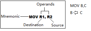
- MOV R1, R2:- MOV is an instruction used to move the data between register-register. It is an instruction with a register addressing mode.
- MOV R, M:- MOV R, M is an instruction, where R is denoted for a register and M is the memory address where the H-L pair is pointing at that time. This instruction copies the data of a memory location (means where the H-L pair is pointing at that time) to a register. It occupies 1 byte of memory.

- MOV M, C:- MOV M, C is just like the instruction we just discussed above, just the data transfer here is from C register to memory. It is also following register addressing mode.
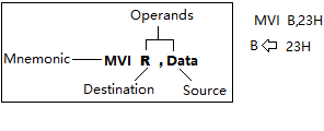
- MVI R1, 23H:- MVI B,23H. MVI is used to move data immediately. Here B is the register, which is the destination, and 23H here is data and this 8-bit of data will go to register B without wasting the time fetching, decoding, and executing. It is Immediate addressing mode.
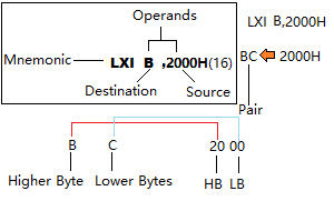
- LXI B, 2000H:- It is Load Immediately. X stands for pair, the first operand here is B, so it means BC pair. Here the BC pair can hold 16-bit of data immediately. ‘B’ represents the higher bytes and ‘C’ represents the lower byte. Similarly, 2000H is data and not an address here. ’20’ are higher-order bytes so they will go in the ‘B’ register and ’00’ will go to the ‘C’. It also comes under immediate addressing mode.
- MVI M, 23H:- It is Move Immediate. ‘M ‘ is memory. Memory is, where the H-L pair is pointing. 23H is the data. SO here 23H data is immediately transferred to memory. It is also following immediate addressing mode.
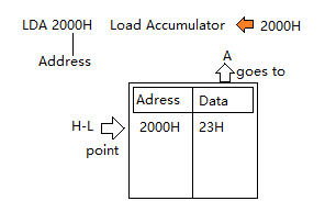
- LDA (Load A):-LDA is Load A where ‘A’ is Accumulator. For eg. LDA 2000H, means Load the data at the address 2000H to the Accumulator. This is absolute addressing mode.
- STA(Store A):- STA is to store the contents of the accumulator to a location address. For eg- STA 3000H. Now according to the previous instruction example, we have 23H in ‘A’. We have now stored this data at address 3000H. This is also following absolute(Direct) addressing mode.
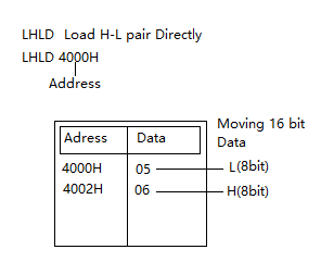
- LHLD(Load H-L Pair Directly): This instruction is using H-L pairs and loads data from a given starting address and data present there is less than 16-bit then pointer moves to the next address automatically and takes data from there too. All data are stored in the H-L pair according to the higher byte-higher address and the lower byte goes to the lower address.
- SHLD(Store H-L pair Directly):-It is like the LHLD but works in a reverse manner, storing the HL pair content at address locations. eg- SHLD 2000H. SHLD is also following direct addressing mode.
- LDAX:- Load ‘A’ ‘X. This instruction is to load the contents of a specified register pair to the Accumulator. For eg- LDAX B. According to this example, we are loading the content of the address where the B, C pair points into the Accumulator. So, if the B, C Pair points to 2000H, the data at 2000H is loaded to the Accumulator. LDAX comes in the register indirect addressing mode.
- STAX:- STAX stands for Store Accumulator into the memory location pointed by register pair. For eg- STAX B. It follows the register indirect addressing mode.
- PCHL:- Load Program Counter with HL contents. The contents of HL goest to the PC, Higher-order bytes are the contents of H and L are lower order. For Eg- PCHL.
- SPHL:-SPHL is an instruction that helps us to Load stack with H-L contents. The Stack pointer register points to the TOS(tops of the Stack). So, the H-L pair contents are now loaded in the data part of Stack Pointer, at the TOS where it is pointing.
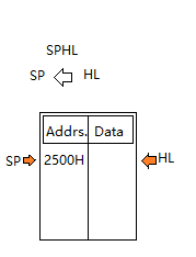
HL data isn’t altered in the SPHL.
- XCHG:- This instruction is for exchanging the contents of two register pairs. We don’t write any operands to specify registers because it’s only predefined for two register pairs HL and DE pairs. eg-XCHG
- XTHL:- It exchanges the contents of SP and HL registers. Contents of address pointed by SP go to HL and Contents of HL go to SP. eg-XTHL
ARITHEMATIC INSTRUCTION SET
- ADD B:- ADD instruction used to perform addition. ADD B is an instruction that performs addition between the content of the source operand to the destination as a single operand. Single operand makes it efficient and reduces the code size. By default, the first operand is already in the ‘A’ and we have just defined one operand here ‘B’.
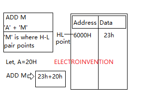
- ADD M:-ADD M means adding the content where the H-L pair points to the content or data in the Accumulator register.
- ADI 23H:-ADI is for Add immediately to Accumulator. In this, we have only one operand ‘Data’ 23H and by default other one is at Accumulator. ADI 23H means to add immediately 23H with the content of the Accumulator register without wasting the time of fetch and accessing.
- SUB B:- It’s for the subtraction of the value in the source operand from the Accumulator. SUB B means A-B, where A is the Accumulator register.
- SUB M:-Subtracting the values of the location where HL pairs are pointing from the contents in the Accumulator.
- SUI 25H:-Subtracting immediately from the content of Accumulator.
- ADC B:- ‘Add with carrying‘. It means A+B+C. If you guys have read about the architecture of the 8085 microprocessor, you should be knowing about the flags register and the 5 flags. Since our microprocessor is an 8-bit microprocessor and we want to add a 16-bit number, we need something to carry and make a record of carrying bits and add it later. The result is again going to be stored in Accumulator. If the carry flag is (CY)= 1, the result is Accumulator+B+CY. We will see some examples of it later.
- ADC M:-ADD with Carry M. Similar to previous instruction but taking a number from ‘M’.
- ACI 25H:- ADD with Carry immediately. A+CF+25.
Similary, we have some instructions for subtraction with borrow, like we have instructions for Addition.
- SBB B
- SBB M
- SBI 25H
- INR:- INR is the increment instruction, that increments the register contents by 1. The contents of a particular register are incremented by 1. eg- INR B
- INX:- INX is also increment instruction but here, ‘X’ is used for register pair. INX increments the contents of the whole pair by 1. eg INX B, let, BC was having 2003, so now it will be 2004.
- DCR:- DCR is to decrement the value of content in a register by 1. eg-DCR B.
- DCX:- DCX is similar to decrement pair value by 1. eg- DCX B
- DCR M(similar, just for M)
- INR M(similar just for M)
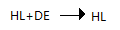
- DAD:- DAD stands for double addition. It adds two 16-bit numbers of HL pair and DE register pairs. The result, in this case, is stored in the HL pair.
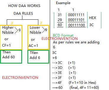
- DAA:- DAA is Decimal Adjust after addition. A computer or a microprocessor works on Hexadecimal. Hence, after an addition operation the value it stores in the Accumulator is in Hexadecimal, which is not understood easily by a normal person.
To make it understandable easily we need a BCD converter instruction to run after an ADD operation. DAA is used for this.
Using DAA the content of the accumulator is adjusted into a valid BCD or decimal number after two Binary or decimal numbers are added. DAA does it by bypassing the Characters coming in the output result and hence giving the required decimal result format.
Below are the rules and steps on how DAA works and also with a given example that must clear all your concepts about this instruction.
Where this is required? DAA is everywhere used in many processors like 8085,86, Pentium, 8051, Moreover calculators you use and other digital devices.
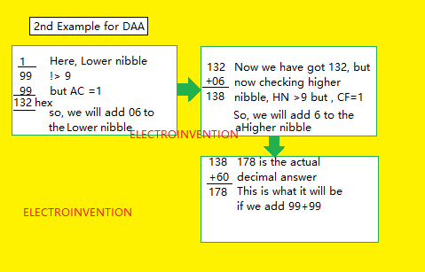
Let’s take another example for DAA
LOGICAL INSTRUCTIONS
Logical instructions are used to perform logical operations.
- ANA R:- This instruction is used to perform the AND operation on register data. It is like AND gate and, ANA stands for AND Accumulator and ‘R’ specifies the register.
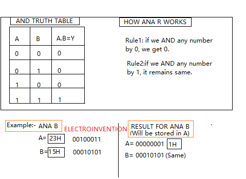
- ANA M:- It’s the same AND A with ‘M’. Here, ‘M’ is for memory, which means where the HL points.
- ANI 23H:- AND A immediately with 25H. Similar but immediately AND contents in ‘A’ with 25H.
- ORA R:- ORA is to perform OR operation between the contents of Accumulator and with the register specified. Here,’ R’ denotes the register. For eg- ORA B.
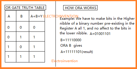
- ORA M:-Similar to ORA R but the difference is, here we’re referring to take ‘M’ as an operand. We have already discussed M.
- ORI 23H:-ORI is OR immediate with 23H(can be any data).
- XRA R:- XRA is X-OR contents or register(R-can be any register) with Accumulator. X-OR stands for exclusive OR. For the same bits, it gives low output and for different bits, it gives high output. eg- XRA B.
- XRA M
- XRI 25H
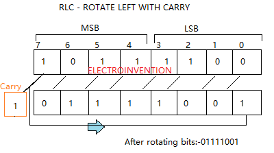
- RLC:- Rotate Left with Carry. This instruction rotates the bits to the left. All the bits move to their adjacent left place displacing the particular bit there. The 7th MSB goes to the Carry and also to the 0th LSB. In this carry flag is affected and whatever was there in the carry flag before this operation will be replaced.
- RRC:- RRC is Rotate Right with Carry. In this bits are rotated to the right, and here the LSB goes to carry, and to MSB also.
- RAL:- Rotate Arithematic Left. Here we have carry bit preserved. In this, the carry flag is also involved in the rotation.
- RAR
- CMP:- CMP, Compare. Compares two numbers stored in ‘A’ and another register by subtracting like A-B. If the result is +ve, then content in ‘A’ is greater. If the result is -ve, then B is greater. If the result is 0 then A=B. This result is not stored in the accumulator, just flags that are affected. If A=B, the ZF(Zero flag is set) is 1 and CF is 0.
- CPI 25H:- Compare immediately.
BRANCH CONTROL GROUP INSTRUCTIONS
Branching instructions are used to control the flow of the program and creating a looping condition.
- JMP:- This instruction is used to jump to a memory location from the current memory location to any other memory location. eg-JMP 2000H.
- JC:-Jump if Carry. It is a 3-Byte instruction. It jumps whenever the condition is met as it is conditional jump instruction so it will jump only if the carry flag is 1.
- JNC:-Jump if NOT carry. It is conditional Jump instruction if the carry flag is 0, it will jump and transfer the program control to the specified address. JNC 2000H.
- JNZ:-Jump if not Zero. Similar to the Jump statement but it only executes if the Zero flag is not set. This instruction is used to jump to the 16-bit address as specified in the instruction. JNZ 4000H.
- JZ:-Jump if Zero. This instruction only jumps to a specified address if the Zero Flag is set or else the program control flows in the sequential flow.
- JPE:- Jump if parity even. It is a conditional jump to a 16-bit address specified in the instruction if the Parity flag at present time is set.
- JPO:-Similar to JPE the only difference is that it jumps if the Parity flag is reset and is having a value of 0.
- JM
- JP
- CALL:- CALL stands for “CALL a subroutine”.It is to transfer the control over another subroutine and start executing that, then return back and start the execution where it left. CALL, PUSH RET, POP work together.
CALL instruction is executed, before any execution, the current returning address is PUSHED at the TOS (Top of the stack). Now, the Microprocessor jumps the control over the subroutine location specified by the CALL instruction.
After the execution is complete now control for execution is returned to the previous execution. This is possible by RET(Return) instruction.
RET stands for RETURN from the subroutine. RET is a 1-Byte instruction.
After getting the address from the TOS(Top of stack), microprocessor resumes its execution in the main program.
MACHINE CONTROL INSTRUCTION GROUP
Machine control instruction groups are basically machine control instructions and mostly are for interrupt controls.
- SIM:-SIM(Set Interrupt Mask) is an instruction used for multiple purposes. It’s 1 byte. The main purpose is to mask and unmask the lower priority interrupts like RST 5.5, RST 6.5, and RST 7. Usually, its main purposes are:-
- Masking or unmasking of RST7.5, RST6.5, and RST5.5,
- To Reset to 0 RST7.5 flip-flop
- To Perform serial output of data
- RIM:– RIM stands for reading Interrupt Mask. It’s a multipurpose instruction used to read the status of interrupts, RST 5.5, RST 6.5, and RST 7.5. It does that by checking the contents of the Accumulator after execution. It is also useful to read Serial Data Input bits. The instruction loads 8 bot data from the accumulator.

- NOP:- The instruction is for nothing but just for the delay. It is simply fetched and decoded.
- HLT:- It is HALT. Used just after the CPU stops current execution, it is used to stop the further execution.
- DI:-DI stands for Disable Interrupts. After this instruction is executed, the interrupt enable flip-flop is reset and all the low priority interrupts are disabled except TRAP.
- EI:-Enable Interrupt is set and makes all interrupt Enable.
So, these were all the instructions of the instruction set. Now let’s take one example and get to know how to make use of them and practice instructions.
8085 PRACTICE QUESTIONS Basics
Q1.WRITE A PROGRAM IN ASSEMBLY LANGUAGE TO ADD TWO NUMBERS STORED AT TWO DIFFERENT MEMORY LOCATIONS, STARTING OF THE PROGRAM SHOULD BE FROM ADDRESS 6000H.
ASSUMPTIONS:-
- The starting address of the program is 3000H.
- The memory address of the first number is 3025H.
- The second number is at Memory address 3026H.
- The memory address of the result should be store 3028H.
| Memory Address | MNEMONICS | Comment |
|---|---|---|
| 3000 | LDA 3025 | A<–[3025] |
| 3003 | MOV B, A | Moving B<–A |
| 3004 | LDA 3026H | Loading to accumulator A<–[3026] |
| 3007 | ADD B | A<–A+B |
| 300A | STA 3028H | [3028]<–A |
| 300E | HLT | Stop execution/ Terminate |
Thanks for taking the time to read, if this was helpful and tell us in the comments section below and also share with your friend. Also, Subscribe to our Newsletter if you want to read more from us.
Exceptionally nice , Ia m from spain
Thanks for visiting.
Too good
Great content! Keep up the good work!
Thanks for visiting and glad you liked it
Tadakta bhadakta ❤❤
Super cool fantastic fabulous damnn.