
Automatic Emergency Light Circuit
Hello Guys, Hope everyone is doing well. Power cuts or routine electricity cuts are common in some places. These things are often common. Also, those who don’t have inverters in their home or a specific area like the garage of out doesn’t have inverter connection face problems in a sudden blackout. Here is a Simple Automatic Emergency Light circuit. This automatic emergency light /lamp is very useful for such a purpose. As, when suddenly Electricity goes, it automatically turns ON and stat providing a bright lumen. Also, it charges when Electricity comes back. So we can say that it’s a smart and very simple useful thing. Also, this project might also be very useful for beginners.
Already there are also some advanced circuits on this site for Solar Automatic Night Lights, Solar Rechargeable lamps/ Lights Circuits. You can go through them. But, this one is a simple straight Emergency lamp circuit, if you don’t want it to be solar.
Discussing further below with circuit diagram of this automatic emergency lamp that auto turn ON.
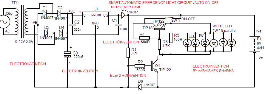
Automatic emergency light circuit
Materials
- D1-D6 1N4007
- Transformer 12v 0.5A to 1A (12v 0.5A transformer buy @ $2 cheap )
- Battery 6V Rechargeable 4.5 Ah
- 1 watt white LEDs 6-8-10 pcs (depending on battery backup available and brightness you want)
- C1 100n
- C2 330n
- C3 220uf
- LM7808 Voltage Regulator(For datasheet LM7808)
- Q1, Q2 TIP122
- R1 5K1 (5.1K)
- R2 680R (680 Ohms)
- R3 4.7K
- R4 680R
- R5 100R(100 Ohms)
- SW1 that is Switch for ON-OFF for turning light ON-OFF
- PCB
Working of the design
So, now let’s further discuss about how this design works and what do it do?
This Design is very simple and uses a simple and effective approach to detect electricity cut-off and start serving automatically. Also, it has option for you to switch the light off if no use or if it is to be carried out somewhere or kept aside.
The circuit is first having a 12v tranformer and bridge rectifier stage at starting, which should be always connected to the Domestic AC supply source. So that, it can detect the electricity cut and also can charge battery, as well as detect electricity supply and turn off the LEDs automatically.
The bridge rectifier stage after a 12v transformer is proving DC supply to LM7808 Voltage regulator. That after that provides 8v 0.5-1A DC to the battery for charging. Usually, after crossing through D5(1N4007) it becomes 7.3 or 7.4v practically. So that’s not an issue.
As we know the current always follows the shortest and easiest path to travel, so the voltage out from the regulator doesn’t go through the R1 and instead, it goes to the battery for charging. And the LEDs are still remained turned off due to inefficient supply to run.
When the electricity is cutoff, now the the transformer is also not getting any supply from the wall socket and aso no power going further to the regulator.
Now, this time the battery isn’t charging and now 6v-6.5 DC from the battery is striking towards the D5 which will not allow it to pass through in reversed biased. Eventually, R1 will be the easiest path and the Q1 (TIP122) is turned ON, by getting it’s base pulled up and biased +ve.
Now, after the TIP122 has become active, it will provide the LEDs in parallel, access to the ground via collector and emitter.
And the switch SW1 should always be kept ON while Plugged in to the wall socket AC outlet. So now, the LEDs are also getting access to the battery negative and getting enough regulated supply via Q2(TIP122) to drive them. LEDs now will glow brighter.
The amount of 1watt LEDs in Parallel must be decided upon the required brightness and the battery backup available.
Like, If you are using 8 pcs of 1watt LEDs in parallel, with having 4.5 ah 6v battery. Then Load = 8w, Total Backup available= 6*4.5=27watts. The total Backup Time available= 27/8= 3hours approx.
This is how you’ll calculate.
Always keep the AC supply and the LEDs switch, both ON if you want an automated process. And this is a great circuit if your area has frequent electricity outages.
Usually, if you have used 12v 0.5A transformer and a 4.5ah battery, then the chances are, the battery will be charged fully after 4 to 5 hours. And if you don’t have that much electricity cuts between 5 hours minimum, then better remove it from wall socket in order to prevent overcharge and turn the LEDs switch off . As, now it’s fully ready to serve you during the electricity outages. Whenever needed, just turn ON a switch and it will start doing it’s job.
If you frequently have electricity outages between every 5 hours or so, then keep it plugged ON to the wall socket and no problem, it will automatically turn ON,when electricity is cut.
I hope you guys have enjoyed it. Do give it a try. If you have any questions, ask me in the comments. Subscribe to our newsletter for more such projects. It’s of course absolutely free, so, do it if you like my posts. Thank You for reading this. Do Comment.
Hey I love this design it is so simple And woks really nice.
hi its nice project. I like your way of explaining.