
Hello Engineers, hope all are great! In this article, we are going to discuss an IR proximity sensor circuit using TSOP 1738 IR receiver. This circuit was made at the request of one of our visitors and is immune to outdoor light or sunlight. This circuit is a bit different than the usual circuits for Infrared proximity sensor modules. The main problem with that module is, the photodiode used in them is not for a particular frequency range. They usually react to any source of infrared radiation.
Please tell us how to make ir proximity sensor ciruit taht work perfectly in sunlight too. with all the necessarydetails. and how its work with all components detailReply
Infrared rays are just a kind of light rays that have an electromagnetic spectrum with wavelengths that are longer than visible to human eyes. But these can be felt in the form of heat.
Sunlight is also a source of infrared rays. Why Sunlight is visible then?
Sunlight that reaches the earth’s surface is constituting of 3 separate frequency bands, UV(Ultraviolet) rays 290-400nm, visible light 400-760 nm infrared light 760-4,000 nm.
This is the main reason that those normal IR proximity sensor modules also sense the infrared radiations in the sunlight. Sensors get confused and don’t work as expected. That’s the reason our visitor Tushar, who is a YouTuber, faced an issue. In this circuit, we have used a different IR receiver photosensor TSOP1738.
TSOP 1738 is an IR sensor that IR signals to electric signals. It operates on a specific frequency. TSOP1738 operates on a 38KHz IR frequency. TSOP1738 doesn’t work on frequencies other than its specified range. Although it can react a little due to leakage current It uses silicon packaging technology. It has an IR receiver and signals amplifier inbuilt. It is able to work between a frequency of 30Khz to 42Khz.
Materials and Components
- TSOP 1738 -1pc
- IC555- 1pc
- C1 100nF
- C2 10nF
- RV1 2K preset(basically consider as R1)
- R2 1K
- 8-pin DIP(to mount the IC on the PCB)
- IR LED (IR emitter led)
- PCB
- R3 100R
TSOP1738 IR proximity sensor circuit diagram
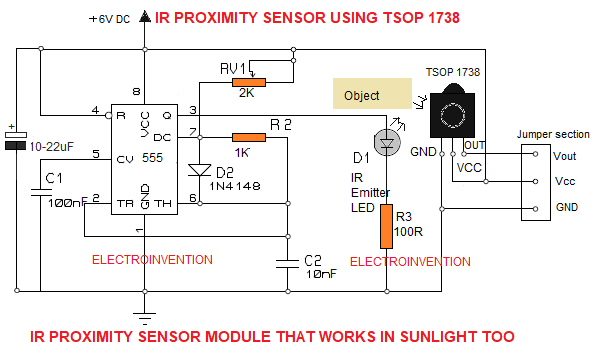
In the circuit above we have used TSOP 1738 to detect the IR light reflected back from the obstacle or object detected.
TSOP IR receivers are specially tuned to only activate at a specific frequency range. For example TSOP 1738 can operate on 38Khz and usually these sensors can operate in a range from 32-42 KHz.
For this we need a transmitter like most of the TV remotes, to emit an IR signal in this range. For this, we have made use of an IC555 AMV circuit to generate the signal at that much frequency.
The resistors, RV1, R2 and Capacitor C2 are responsible to help IC555 achieve that. Check IC555 Astable Calculator .
The pin 3 output gies to an IR emitter LED, usually you can find it on your TV remotes, DVD,VCD, Car Sterio remotes.
This electrical signal is now converted to the IR light at a frequency range from 36KHz to 48Khz, more or less, depending upon how you set the preset RV1.
You can set the sensitivity of the circuit and also the compatibility of the circuit with your IR receiver sensor by adjusting the 2K preset.
Whenever the IR light emitted from the emitter strikes any object, it gets reflected back to the IR receiver(or photo diode), this the allows the TSOP receiver to give an output voltage accordingly to the strength of proximity.
This output can be directly used with any TTL or CMOS devices, any microcontroller as well. It gives a digital output of 1[HIGH] or 0[LOW] whenever an obstacle is detected.
It’s better to use an LM7805 voltage regulator to give VCC to the sensor whenever you go above 5 or 6V DC. I prefer to use a voltage regulator for the sensor always so that you won’t burn it.
The output can be derived from the ‘Vout’ pin of the TSOP 1738 as shown in the circuit.
Thanks for reading. If you guys have any doubts, you can ask in the comments.
Thank you.
Sir how will the circuit work because the tsop1738 rejects the continuous input of 38 khz so if we were to do continuous proximity sensing then this circuit would not work kindly explain the way out of this
really thank you so much for this
Thank you so much for this project this is very usefull and easy to understand
Hello Tushar, I am glad you like it and looking forward to seeing how you do it on your youtube channel.