
A rectifier is a circuit that converts the ac input to a DC supply.i.e from sinusoidal, square, or triangular waveform to a unidirectional constant waveform. I have discussed 3 types of rectifier circuits in detail and their circuit diagram and their output waveforms. “Different Rectifier Circuits”. different types of rectifier circuits.
Halfwave rectifier circuit :
How does Half wave rectifier work?
A halfwave bridge rectifier is one that has only one rectifier diode employed in its circuit for rectification. Since the Schottky diode is used in rectifiers, so it conducts only in forwarding bias only. Due to this only one-half wave of AC input is rectified and converted to DC and the other negative half-wave is un-rectified. This kind of rectifier circuit is dangerous if used with delicate or sophisticated electronics. It has the highest level of distortion in its out put.below is a circuit diagram with simulation output waveform snaps.

OUTPUT WAVEFORM

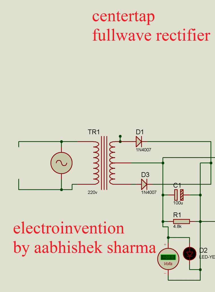
2. Center tapped full wave rectifier:
This is the full-wave rectifier, but this one uses only two diodes with a center-tapped transformer and rectifies both, the negative half and positive half of the input both.
3.Full-wave bridge rectifier:
This is the most powerful and effective Full-wave rectifier circuit. It has 4 diodes and its output waveform is much cleaner. It is required when there is a high power requirement or for much reliability. This one is a better and most safer form of the rectifier circuits. It rectifies the both halves of the sinusoidal input.

The output waveform of a full-wave bridge rectifier without filter circuits

You can add more precise filters like LC, CLC to get more correct waveform. I HOPE YOU GUYS LIKED IT. If you liked it please let me know in the comments. If you have any doubts you can ask in the comments.
VIDEO Link:
making a full-wave bridge rectifier
In which circuit will i get better results. Full wave center tapped rectifire Or full wave bridge rectifire…. And waht about halfwave rectifire with single diode is it useful I any application since it conducts only forward bias using schottky diode??
Hi Rishi, thanks for visiting. Among the center-tapped and the full-wave rectifiers,full-wave is better than any rectifier.
For second part of your question I have mentioned in th article that its the most inefficient circuit, though they were used in some of the high immune unsophisticated applications but these days halfwave rectifiers aren’t used as mot of the devices are now more sophisticated and require pure clean power.The full-wave bridge rectifier is the best rectifier amongst all. You can add some filter components before output RL to get a more clean and pure DC.