
Hello People, Sometimes our batteries in go-carts, inverters, kids buggy toys, emergency lights, etc after a long period of inactivity resist to full charge. They may also stop charging completely or their supply quality degrades to a greater extent. This is due to battery sulfation. In this article, we will discuss more about the battery sulfation and How to recover Lead acid battery from sulfation. I have also explained a battery desulfator circuit. I have mentioned a simpler circuit to charge a sulfated battery. Let’s start with our topic, ” RECOVER LEAD ACID BATTERY “, ” Battery de-sulfation circuit “.
What is Sulfation?
Sulfation is a state occurs when a battery is deprived of a full charge, a layer of lead phosphate occurs crystals around the electrodes and remains on battery plates. Batteries create sulfation each time they are used (discharged – recharged). If they are overcharged or undercharged or are discharged for a long time, they will rapidly develop sulfate. Even if a battery is stored fully charged, sulfate will form unless a desulfation battery charger is used.
Lead and lead dioxide, the active materials on the battery’s plates, react with sulfuric acid in the electrolyte to form lead sulfate. The lead sulfate first forms in a finely divided, amorphous state and easily reverts to lead, lead dioxide, and sulfuric acid when the battery recharges.
Using or storing batteries in temperatures above 75°F accelerates the rate of self-discharge and increases battery sulfation of battery.
What is desulfation? How do battery desulfation circuits recover lead acid battery?
Desulfation is a reversal process to remove sulfation from a dead or sulfated battery. Desulfation is to restore a battery by breaking and removing the lead sulfates crystals from the battery electrodes, either fully or partially.Desulfation either restores the battery to it’s full potential or upto 60-70% sometimes. Perhaps, there is no such specific percentages, but, though it works very well. Sometimes fully and sometimes almost.
Battery desulfation can be achieved by using battery desulfator circuits. This involves applying constant high current pulses to the battery terminals. This is called the battery conditioning method. It breaks the sulfate crystals which are formed on the battery plates. This method is probably very good and one of the best.
Steps to follow:-
- STEP1: Take the battery and note down its initial voltage.
- STEP2 Remove its case if its an SLA(Seale Lead Acid )battery and open the vent caps.
- STEP 3:After you have removed the case and vent caps are off now. Use a dropper or injection syringe and fill each cell with distilled water (De-ionized water). (Remember not to fill it with tap water otherwise it will damage the battery’s electrodes.).
- STEP 4:Wait till each tube gets the water mixed with dry acid and bubbles gets down.
- STEP5: Charge the battery with a battery de-sulfate charger circuit for some 5 hours then check the voltage constantly using a DMM.
- Remember that the battery’s connecting time will be according to the battery size(ah), charger output power & how long it takes for the battery to come at its healthy output behavior.
IC555 Battery Desulfator Circuit
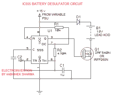
Materials
- IC555 – 1pc
- R1 10K
- R2 470R
- C1 1uf Poly capacitor 63v
- C2 10nf
- Q1 IRF540N or IRFP260N for batteries bigger than 26 ah
- D1 Use any 6amp Rectifier diode ( for eg. 6A10)
- Transformer 18v or 24v 5amp-8amp
- Rectifier circuit with 6a rectifier diodes
- LM338
Working
The Circuit above is an effective and simple battery desulfator circuit. The circuit is above is a high current IC555 pulse generator with a higher frequency. For the above desulfator circuit, we need to make use of a suitable rectifier and transformer with an adjustable voltage PSU circuit. So, that we could get the higher current and desired voltage output to feed into the desulfator circuit.
For Higher current, I suggest a powerful transformer with a current up to 5 amp and 6A rectifier diodes. To adjust the output voltage and provide a higher amp output to the desulfator circuit, I suggest using the LM338 High amp variable power supply circuit. LM338 has the potential to go at a range 2A- 5amp, with an output voltage range from 2 to 35V dc. Input must be always 2 volts more than the required output voltage like to get 15v, you must input 18v or can be higher.
The High current 15 v input is then fed to the desulfator circuit which then generates pulsed output at a higher current & a frequency at 130Hz. 130 hz high current 2-5amp input can effectively remove and zap out the lead sulfates that was hardening over the battery plates.
This then enable the electrodes to react with the acid and also to work efficiently.
Before connecting to desulfator circuit, don’t forget to fill up each battery cells with the distilled water till the top(but not overflow).
Charge at least 6 hours ( 6-12ah batteries) then check the voltage if it’s above 13.5v. Also, put an ammeter in series with the charger and the batteries positive terminal.
Also, put an ammeter in series with the charger and the batteries positive terminal. Observe it if the current is increasing and is going up to the initial rated current of the battery then it’s a positive response.
Cautions:
- Remember, It’s Not for kids, Only experienced hobbyists or professionals do this.
- Make sure you wear proper glasses or something to protect your eyes and face when filling de-ionized water.
- Don’t keep your face above the battery while filling it with distilled water.
- Fix the battery vent caps and covering perfectly after filling.
- Charge at least 6 hours ( 6-12ah batteries) then check the voltage if it’s above 13.5v. Also, put an ammeter in series with the charger and the batteries positive terminal. Observe it if the current is increasing and is going up to the initial rated current of the battery then it’s a positive response.
- Keep away don’t be too closer to the battery as no one knows and there is no specific way to tell if it’s really a bad battery, you should not get any fatal injuries if something you did wrong.
I hope you guys liked it. I HAVE ADDED A VIDEO LINK FOR IT TO MAKE YOU UNDERSTAND MORE CLEARLY. You can watch the video by clicking here. The circuit in the video is different, but I prefer this one over the one shown in the video. THANK YOU FOR WATCHING.
Hi sir i have build this 555ic desulfator circuit. I can see it is charging the battery with 18v input and regulator set to 14.2v. Output after diode is 13.6v , that right. I have no scope to check the pulses spike voltage. I do not think it is high enough to break down the sulfate. Is there a mod for this with out using coils.
I am using two transistors and a potentiameter as regulator and the desulphator
circuit is connected to a 100AH battery.
Emmanual please use a proper regulation circuit that provides adequate output power in order to drive the circuit safely and also to handle the battery of this much big 100Ah battery.
Can you upload a picture somewhere and share the link here. Because I don’t know the transistor you’re using for the regulation. Moreover, it is also not delivering that much power.
Which MOSFET are you using?
It must definitely work.Try adding a 100 ohms 1/2 watt resistor between ic pin 3 and mosfet.Make sure the components you using are nit reused and are fine.
Try using it with a small battery too.
Send me full details like component and connections.
My ic555 is heating up just after switching on. Should I put a 12v zener diode. I leave in an area we don’t have Power grid, so I am using 100w solar panel connected to a simple regulator to power the circuit. What should I do sir?
Hello Emmanuel,100watts is like more than 6 +amps at 15V I even doubt if it’s proper regulation. Make sure you have used all the correct components and no reused components. I don’t even know what kinda regulator you’re using. It should be only up to 2 to 5Amps max. safer is 2 or 3A. Use a suitable regulator first.
First, connect the circuit to a battery, Then only Turn the circuit ON. It should work cause some people tried this and all of them are working, Even the same design is having a lot of working videos on youtube. So try checking all the connections and make sure you used correct components.
I made the desulphator circuit but its not working. Sir, which points should I measure to know if the circuit is working. At the output I am only getting 14.4vdc the input voltage is 15vdc.
Hello Emmanuel, if it’s giving a 14.4V DC output then it’s absolutely working. Your Question is why you are getting the only 14.4V with 15V dc at the input. This is because of 0.7v threshold voltage by the diode is deducted from the total input.
Although that’s not a problem. To desulfate a battery with this, follow all the instructions given and it’s gonna work. Make sure you put adequate input power. Good Luck! It’s already working if you’re getting the output
The topic Recover Lead Acid Batteries was well written and thank you so much for the information and the circuit.
Hello Emanual, thanks for coming here. Glad you liked it.
Have you tried it yourself on any battery
Hello Ganai, thanks for visiting, and yes the circuit is tried and tested, you can also find some little bit different but similar approach circuits on youtube to check their live performance.
ThankYou
thanks for this usefully circuit.
Hello Bruno, Thank for visiting again. And glad you liked it.
So when distilled water mixed with the old acid in the battery cant be weak?
Hi, Adolph, thanks for visiting, the distilled water is used to re energize the dried acid, acid doesn’t get weak by water. It increases and dilutes. But any battery can’t be fully desulphated. This method only recovers the battery 50-70%.
Amazing next bolg on lithium ion battery
And if possible please try to explain the mechanism
Hi, rishi,
Good to watch you again , sure I will soon upload an article over it.