
Hello engineers. Hope all are good. In this article, I am going to discuss a very simple IC555 based timer alarm circuit that can have a time duration range from as low as 5 minutes and as high as 30 minutes. In this timer based alarm circuit, you can select the alarm time delay duration.
There is incorporated a 4way rotary switch in order to select the particular time duration and 1 push button to activate the alarm after selection.
Timer selection option available are 5, 10, 15, 20 minutes or even 30 minutes. You can even increase the time up to 1 or 2 hours. We’ll discuss that, ‘how’ later in the article.
We have here used the IC555 in a monostable state. This time duration and all the components are calculated we can discuss that later in the article. So let’s move further.
Materials
- IC555 Timer
- SW 1 normal slide switch
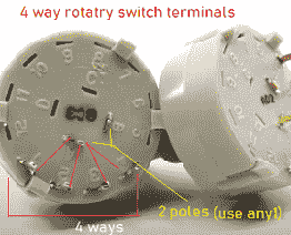
- 4-way Rotary Switch(1 pole or 2 poles, doesn’t matter you have to use one)
- C1 520uf
- C2 100nf (0.1 uf)
- R1 27K ohms
- R2 500K
- R3 1M
- R4 1.5M
- R5 2.2M
- Q1 BC547
- Relay 12v SPDT
- 12VDC supply
- D1 1N4007
- 1 push Button
Circuit Diagram for IC555 timer alarm circuit
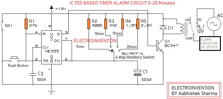
The circuit above is simple and just needs a 12V dc supply input. There is a switch SW1 to turn ON/Off.
Here we have used IC555 timer monostable oscillator for the control. There is a Push Button to trigger the negative pulse to the PIN2(trigger) of the monostable configured timer IC.
The Monostable 555 Timer circuit gets triggered on a negative-going pulse applied to pin 2 when the push button is pressed and released.
This trigger pulse must be much shorter than the output pulse width allowing time for the timing capacitor to charge and then discharge fully.
After getting triggered, the 555 Monostable circuit’s output will remain HIGH unstable state until the time period set up by the R1(R2 to R5, IN OUR CASE) x C1 network has elapsed.
This output pulse will stay high based on its pulse width. This output pulse width sets the pre-defined time and as said earlier it can be set by selecting the correct values of Resistor R1 (R2 to R5) and Capacitor (C1) using the below formulae. A circuit is shown below for calculation purposes.
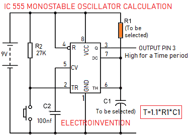
The time delay in a monostable mode is calculated as per the formulae: Or use https://www.electroinvention.co.in/ic555-monostable-calculator-circuit
Output Pulse Width in seconds = 1.1 x R1 x C1
In our circuit, there are R2, R3, R4 and R5 that can be selected by the help of rotary switch.
You can also use normal switches and wire them the same way with one end separately to each resistor and the other end common with all other switches connected to PIN 7and 6 junction.
All those resistors in the circuit are accurately calculated by the formula 520uf capacitor above and tested separately so the circuit is tuned and performs according to the resistor selected.
Let’s check it by an example :
Let’s say R1 = 500K ohms -> 500000 Ohms
Capacitor = 520uf -> 520 microfarads = 0.00052 farad
So, output pulse width high time = 1.1*500000*0.00052F = 286 Seconds i.e 4.76667 minutes which is approximately 5 minutes.
So that’s how you can also check the resistor value and capacitor value according to you High time requirement.
When the circuit SW1 is turned ON, the circuit is on initially the IC’s pin3 is low. You can use the rotary switch or slider switch to select a particular resistor.
To activate the alarm, you have to press the Push Button once and release it, to provide the trigger and activate the alarm.
When the circuit is just ON(SW1 On but alarm not activated), the PIN 3 is not high, so the Q1 is also not activated and hence the relay is also OFF. This makes the device is connected to NC, You have to press the Push Button once and PIN3 goes high. This makes the transistor to get Base current that makes it to turn ON the relay.
After the relay is ON it disconnects the alarm or device Off the supply for a certain time duration. This time period is dependent over the resistor selected by the rotary or slider switch(depends on you, whether use one rotary selector switches of multiple slider switches) calculated by the formula above.
After that time period, the PIN 3 again goes LOW and hence the relay is OFF makin the device/ alarm/ siren to get the supply.
I hope you guys have understood it well and now can also increase the time by using that circuit and formulae.
If you guys have any kind of queries or doubts , or if you liked it do comment below.
Thank You.
That’s so nice and easy. and very well explained.
Yes