
Hello Engineers. I hope all are fine. Guys, Today in this article, I am going to discuss a digital Electronic Pushups Counter circuit. While doing push-ups or any exercise, we need to focus on ” quality over quantity ” i.e focusing on the body form and positioning. Although, still quantity is also required to progress day by day and to track progress. During a workout, let’s only focus on our body form and perfection and let the counting work to be focused by a Digital Electronic pushups counter. Here I have made an Electronic Push-ups counter circuit that is to be placed under your chest while doing Push-ups. This circuit will automatically count Push-ups after keeping an interval of 1 or 1.2 seconds between each pushup.
Let’s discuss further in detail with our electronic pushups counter circuit about how I designed, working and components, etc about this Digital electronic pushups counter.
Components Required and Materials
- IR obstacle Sensor/Proximity Sensor( 2 Pcs IR Proximity Sensor)
- IC 4026 2-pcs
- 16 Pin DIP connector/ 16-pins IC base- 2 pcs ( for mounting ICs )
- R1 680R
- R2 10R
- 7-segment Display Common Cathode
- 6v-9v Battery (Rechargeable would be better)
- PCB standard Size
- C1 330n
- C2 100n
- Lm7805
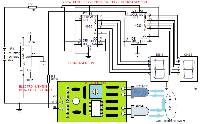
Circuit Diagram – Digital Electronic Pushups Counter
Working, Design & How to use?
The design above is using one of the best and simple approaches to detect and count the push-ups. I have used an IR Obstacle Sensor that detects the pushups by sensing the object(chest/ body) and measuring the proximity. Also, IC4026 decade counter and 7segment common cathode Display are used to count and Display the countings. This circuit is able to count 99, useful for most people because not everyone can do that much pushups.
To understand the PIN outs and working of IC 4026 and 7 segment display follow here.
To understand this circuit’s working, you must know IR obstacle sensor’s working. Follow up this article for that. Basically, in an IR obstacle or IR(Infrared) proximity sensor, there is an IR Sender LED and an IR receiver(Photodiode) that recives, with a couple of other components like ICs or transistors.
In the circuit, there is a 9v power source that can be a rechargeable 9v battery for better power and backup too. I have used the LM7805 voltage regulator to supply the 5V input voltage to the IR sensor module. On the other hand, 9v battery is supplying to Both the ICs that are IC4026 and the 7segment display module.
When power is given, the ICs are initially turned ON and the other side the Sensor is also turned ON.Put the IR sensor module with the sender and receiver in the upside direction so that it could be kept under your chest while doing push-ups.
Adjust the detection range as low as 4 to 5 by varying the preset available on it.
Now IR sender LED is constantly emitting Infrared light, which strikes on your chest or cloth when they come in range when bending elbows down. That IR light is reflected back and sensed by the IR receiver LED of the sensor.
After this, now the sensor then gives a TTL 5v output to the IC1’s CLK(clock pin)pin 1. (IC 4026 at right) for once. Now the counter is incremented by 1 from 0. So, now the 7 segment LED display connected to it shows a “1”. After a delay of a 1-second sensor stops giving output until this next push-up comes and chest again comes in range. Now again transistor senses and again gives a 5V TTL to the IC1’s clock pin constantly for 1 second. Again the counter is incremented by +1 and the display connected to it now shows 2 and the display at IC2 is still at ‘0’.
Both the display and ICs are connected in an IC 4026 visitor Counter with a 7-segment display configuration.
So, each time an input pulse is received at the CLK(clock pin of IC1 4026, the counter will increment by +1. This is how it’s measuring the number of pushups in a very consistent manner.
Make sure to position the sensor in an upside direction so that its emitter and receiver are facing upwards towards your chest. Also, make sure to set the detection range to very low according to your suitability. I suggest as low as 4 centimeters.
You can reset the value of the counter by turning the circuit ON or OFF. Or you can add the reset button feature to the circuit. For doing so, follow the small configuration I have shown below.
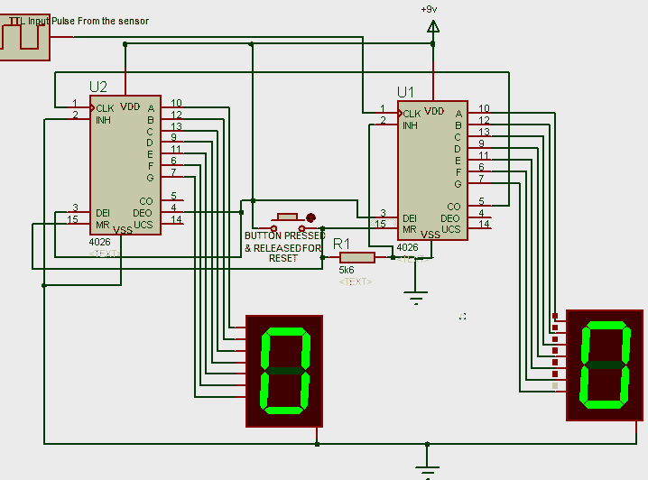
In the Above reset feature, we have this time made use of Pin 15 ( MR pin) i.e Memory reset pin of IC 4026.When this pin of IC goes high, the counter is reset to ‘0’. I have made use of a push button to do that. In the circuit, the MR pin of both the ICs is grounded usually as to keep counter incrementing and use memory. Here 5K6 or 5.6K ohm resistor connecting them to the ground. When the button is pressed and released, the the MR pin is pulled up for a moment and memory data is reset, after released the its pulled down to ground by 5.6K ohms resistor again.
So, using this, you can add reset button feature to it. Rest, everything I have explained. Hope you guys liked it.
Tell me in comments. If you like my content, then do subscribe to our newsletter, it’s free!
Very nice and very easy and intresting design. I will try to make it.