

Hello Engineers. Hope all are great. We have already done the Automatic Night Light circuit on this website. Those were very easy and useful circuits using just a few components and worked just fine. But, here in this article we’re gonna discuss an Arduino automatic night light circuit using Arduino Uno and also an Automatic night light circuit using Arduino Nano boards. We are going to discuss both the circuits as well as practically using Arduino Uno and Nano. With a full detailed circuit diagram, Code, and Real working CIrcuits, Videos using both Arduino Uno and Nano.
So let’s get started with our Arduino Night light tutorial.
Materials Required
- BreadBoard/ PCB
- Q1, 2N2222 or 2N3904
- Relay 5V/ 12V (we have used 12v)
- R1 10K resistor
- D1 LED-RED
- D2-diode 1N4007
- Arduino Uno R3 or Arduino Nano
- Software Tools-Arduino.ide Download Here.
- 12V Power Supply 1A (Either from an adapter to power both, the board, and 12 V relay), 5V USB for Arduino nano
- 220R resistor
- Misc. Male
- Here is a recommendation for various Arduino Starters Kit
Automatic Night light using Arduino Uno
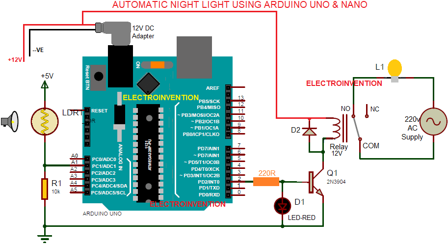
Working of the Circuit
In the above circuit, we have used the Arduino Uno, but this can be done with Nano as well. The pinouts and everything are the same except for the number of PINs and Power specs.
We have used Arduino Uno and have powered it with a 12V 1A DC Adaptor via its DC jack. The same positive +12V line also goes to the 12V relay’s another PIN of the coil.
The analog PIN A1 is set to be the signal reading PIN to get the varying current input from the LDR and 10Kilo ohms PULLDOWN resister’s voltage divider network. With the varying intensity of the light falling over the LDR, its internal resistance is also changing constantly.
As we already know LDR(Light-dependent Resistor), has an internal resistance that keeps on varying with the intensity of light and dark. When the light falling over LDR increases, its resistance falls down to a few 100 ohms from 1M Ohms. And with the increase in the darkness, its resistance keeps on increasing and to the highest range.
The output of this LDR and 10k resstor’s network is read by Analog PIN A1.
Now, it comes to the output pin and we have used Digital PIN 2 to control the LED and the relay according to the input signals and the logic given by the programming. Of course, you can use any PIN, or if you want any PWM control then you may use any PWM PIN. We just wanted to trigger the relay so we used PIN 2.
The PIN 2 gives a 5V output to the Transistor 2N3904 base to activate it. After the transistor is turned on, now it activates the relay through the collector. The 4.3V DC after the transistor is not enough to trigger that relay. So we have taken +12V positive in common coming from the 12V 1A supply.
You can also power the Arduino with the USB cable and use an external 12v Supply for the 12 v relay. Just make sure you make the emitter connected with the Arduino’s ground common with the 12v power supply’s ground.
Also, check the videos and images. Make sure you subscribe. The below video shows how I used Arduino Uno and LDR with a 12V relay for this automatic night lamp that the 220V AC load turning ON when the room’s lights are turned off and OFF when the room’s lights are turned on.
Code for Arduino automatic night lamp
Here is the code below, with each and every of it’s components clearly explained.
int IN;
int Out = 2;

void setup()
{
  Serial.begin(9600);
  pinMode(Out, OUTPUT);
}

void loop()
{
  IN = analogRead(A1);
  Serial.println(IN);
  delay(100);
  if (IN <= 120 )
  {
    digitalWrite(Out, HIGH);
  }
  else if (IN >= 200)
  {
    digitalWrite(Out, LOW);
  }
}
So the above code is very simple and easier to understand.
Looking from line1 and 2 of the code, “int IN;” and int OUT=2; The “int IN” is the variable declaration for taking the input and will be assigned a pin later in the code.
“int OUT=2;” declares the variable “OUT” of int datatype to take the input from the assigned PIN 2(Digital Output pin).
“void setup()”, a void is the keyword to used in declaring functions with Arduino.ide. “setup()” is an inbuilt function that is at the start of the Arduino sketch(in arduino.ide, a program code is called a sketch). It runs at the start of the sketch and here we used to initialize the pinModes. Like which pin is gonna be output or input and what pins we’re going to use. Here we write code that we want to run just once, as soon as the program is executed.
“Serial.begin(9600)”, serial.begin() is used for the serial data communication between the Arduino board and other devices like a PC.
Used to allow Arduino board to send and receive serial communication through a Universal Serial Bus according to the set bits per sec according to the baud rate defined. It allows Arduino to communicate with the serial monitor so as to read the data and show it on your screen.
9600 is the specified baud rate, means the speed or rate at which it transfers the bits..
pinMode(out,OUTPUT);, pinMode() function is used for specifying or configure the behavior output PIN so this makes sense to be in the void setup() function.
Here we have used the ‘out’ variable to specify which pin gives the OUTPUT we know we have assigned 2 as our digital output PIN.
OUTPUT is to define it as an output pin. It is the mode parameter.
pinMode(pin,mode); , pin and mode are the parameters.
void loop(), is the function where we write the instruction that we want to be performed in a loop. This means repeatedly every time a particular piece of code keeps running. Here is the main part of the code. The actual tasks.
The code starts running after the ‘{‘ curly braces from line 1 and runs instruction by instruction till the last line till last ‘}’ curly braces and again starts running from first line of the loop function.
IN=analogRead(A1);, here we have used the analogRead() function to read the analog input value coming at pin A1 and the result is in the variable int IN.
Serial.print(IN); is used to print the serial port data to human readable format. We will discuss that later.
delay(100); it displays the values with a delay of 100 microseconds.
if((IN)<=140){ here we start the if statement and put the condition according to the values we are getting to our serial monitor, we are getting from the serial port according to the analog data read by the pin A1.
These values keep constantly changing according to the intensity of light we are getting on our LDR and printed continuously with a delay of 100 microseconds to our monitor.
If the condition is matched then statements inside the if curly braces are executed. digitalWrite(out,HIGH); to make the digital PIN 2 ‘HIGH’. HIGH is 5V dc.
else if (IN>200){ here is we have the second condition if the value is higher than 200 or same, then pin 2 output will be ‘LOW’. That means 0V.
There is a range LEFT between 120 and 200. So that there is no flickering of the output.
If you don’t want to use that else if statement, simple use ‘else{statements;}’.
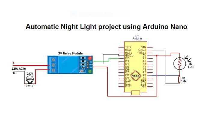
In case you are not having Arduino UNO, or just don’t wanna use a 12v relay, you can do it with a 5v relay, check the video below for my friend’s channel.
Make sure you follow the exact steps and correct the circuit diagram. In case you face any kind of problem with it, feel free to comment below. Scroll down, you will find a comment section.
Hope you all liked it. For anything you have in your mind, you can ask in the comment section below.
This Is What I Want Bro Really Awesome Way To Explaination Keep Going Bro Wating For More.
Hello Tushar thanks for visiting and glad you liked it.
thank you for this I now know how it actually workes with code.
Hello Technical Raju, thanks for visiting.