
Hello Engineers. Although we take many preventive measures and remedies to maintain proper hygiene. Of course, proper hygiene is necessary for good immunity and health. Especially during this coronavirus period, we need to take good care of our health and hygiene. Already everyone is using sanitizers, disinfectants, etc.to disinfect everything to prevent the spread of viruses and infections which harms the immunity. So, there are many options and products available in the marketplace. But what about your home’s bedsheets, sofa-couches, mattresses, etc. Or, for.eg in public transport, the seat covers are also for sure not germ-free. So, today I am going to discuss a new circuit of an Ultraviolet light virus killer device. The circuit is using 3pcs of 10V 3W UVC Ultraviolet lamp. Moreover, it only glows when it detects a nearby surface in range. So, let’s start with our topic ” Ultraviolet light virus killer device” or Ultraviolet light virus killer device | UV-C disinfection.
What is Ultraviolet light or UV Rays?
Ultraviolet Light or UV rays are electromagnetic radiation with a wavelength ranging from 10 nm to 400 nm from frequency approx. 30PHz to 750THz which is shorter than visible light but longer than that of visible light. The electromagnetic spectrum of UV light falls between visible light and X-rays. Ultraviolet rays are present in electromagnetic radiation from the sun. 10% percent of electromagnetic radiations from the sun are constituting UV rays. Although, lowest visible wavelength limit to human eyes is 400nm, so UV radiations are invisible to human eyes. The human eye’s lens blocks an almost 300-400nm range of UV. Some animals are able to see and perceive a part of UV rays.
UV radiations are present in sunlight as well as can be emitted by electric arcs(like welding) or by some special UV generating lights.
If UV light is invisible to the human eye, then how are the light from UV LED s and UV lamps visible THEN? What is that?
The special lamps and lighting rated to emit UV rays are emitting UV light as they are rated, but this is the light that is not visible to our eyes. The light we see from UV lamps is not that UV elements/ stuff. The visible light is the additional lighting which is due to frequency distortion/reflection or by heat. But with regards to UV rays, it is not visible to human eyes.
UV lights are useful for many purposes like:-
- They are used in hospitals to sterilize surgical equipment.
- Disinfection and deactivating bacteria. Used to kill viruses and germs.
- Skin exposed to UVB, also this can stimulate the generation of vitamin D.
- Florence, Used at crime spots to find very minute details.
- Forensic use.
- Cool lighting stuff.
- Treatments of some health issues.
How are UV rays able to deactivate microbes/kill germs?
Hospitals use UV light to disinfect and kill germs very effectively from various surfaces. There are 3 main categories of UV light respectively, UVA, UVB, UVC. UVC has the shortest wavelength and therefore higher energy levels. UVC has a wavelength between 200-400nm. Short-wavelength UVC is the most damaging type of UV radiation. The shorter the wavelength, the more harmful the UV radiation. However, shorter wavelength UV radiation is less able to penetrate the skin.
So, UVC are highly effective and useful for disinfection and killing germs. This process is called as GERMICIDAL IRRADIATION. Due to this high energy UVC breaks the cell walls of microbes that destroys them.
UV rays are also reffered as chemical rays as the can cause surfaces to change chemically.
The circuit for UV disinfector and virus killer device:

Materials:-
- D1-D4 3 Watts UV LED 395-400nm(buy banggood | reference link -nonprofit link)
- Q1, Q2 TIP 122
- R1, R2 510R
- R3, R4 100R
- C1 100n
- C2 330n
- C3 2200uf
- IR Obstacle sensor
- 11.1v Lipo battery
- DC Female Barrel connector/jack( buy from amazon @ $0.9 = Rs 69 INR)
- LM7809 voltage regulator
- Small Heat sinks for both TIP 122
- 3pcs of E17 Intermediate Base Lamp Holder
So, as it is already clearly mentioned we have used 3pcs of 10V 3W UVC Ultraviolet Germicidal Disinfection Lamps/bulbs lights to emit UV rays. The circuit is being powered by an 11.1v lipo battery as the main power source. This circuit has an advanced functionality in addition to emitting UV light the circuit only emits UV light when it detects any surface near its detection range of a few centimeters. If any surface is detected by the IR obstacle sensor adjacent to the lamps panel, then only each lamp is able to emit the UV light. The IR sensor, on detecting a surface gives a TTL output to the base of Q2 TIP122. The Q2 then activates and now gives the lamp’s and Q1’s connection access to the (-ve) ground.
The Q1 TIP122 is there working as the driver for LEDs as well as regulates the voltage from 12v to 9.6v. The charging of the Lipo batteries can be safely done by any 12v 1A rated broadband landline charger DC Adapter as the have auto cutoff and are also suitable for charging those lipo batteries.
A pictorial visualization of the whole design and circuit structural organization is shown below. That is up to the imagination and one’s fabrication techniques on how to make the architecture. Below is how I simply imagined.
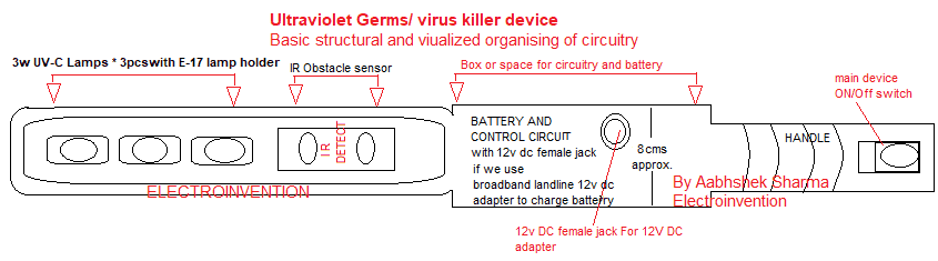
So above Pictorial visualization is just an example and overview on how to place things and especially the sensor and lamp panel and the batteries and circuit accordingly.
SOME IMPORTANT NOTES AND CAUTIONS:-
- Only use UVC lamps that are recommended to be used.
- Do not put light rays comming from the bulbs on your hands, skin or any other body parts.
- Place lamps and lamps holder in the casing in such a way that light should fall on the surface and not be on your hands.
- This is not for kids.
- Note: Please attach and put lamps panel in such a way that UV light emitted by lamps should be only at the surface on which it is supposed to befall. You can use mirror plates or reflectors so that it doesn’t fall or come in contact with human skin.
So, guys, this was all about this circuit project idea. I hope you guys liked it and will let me know in the comments if you have any questions regarding this or any other topics or circuits on this site. The comment section is free to comment guys.
And if you like my work then you can subscribe to our newsletter for the latest posts automatic updates to your inbox.
Muchas gracias. ?Como puedo iniciar sesion?
Explain Q1 and the nearby resistors on the UV virus killer.
Explain in detail please the use of each resistor.
Hello Ravindra, Q1 (TIP122) is an emitter follower voltage regulator to drive the UV lamps. Also, it’s to control the UV lamps ON -OFF only when Q2’s collector gives R2 AND R3 junction. So that, when Q2 is ON, then only this emitter follower circuitry is ON( as it Q2 provides it access to -ve of battery or ground and the circuit is completed).
The resistors R1, R2 near Q1, are also for adjusting the output voltage. The benefit of this kind of configuration is to have a regulated voltage output and it also allows higher current loads to be used at the outputs, moreover, the input voltage has no restrictions and may be increased as per the BJT’s handling capacity and by some minor tweaks in the resistor values.
You can use a POT of 10K or 5K (test it practically) to have the desired output with any input voltage.
Thanks for visiting, Stay connected.
Woah! I’m really loving the template/theme of this blog. It’s simple, yet effective. A lot of times it’s tough to get that “perfect balance” between user friendliness and visual appearance. Additionally, the blog loads very quick for me on Chrome.
The articles are also very good on your blog. Nice
Excellent Blog!
Hello, Thanks for visiting.
Hey aswin here, its a cool idea. there are many stuffs like thhat on internet but this one is realy using certified uvc lamps and also you have given additional info about installation and cautions. Thatis a good thing mate.
Hello Aswin, Thanks for visiting. Thanks for the appreciation and yes I have designed it with certified lamps only and also have given data and cautions about the structural organisation to prevent human hazards and better efficiency and consistency.
Thank you for taking the time to make this circuit.
King regards,
Abildgaard Duke