
Hello Engineer. ” Touch on-off switch circuit “, today’s topic. On this site, Earlier I have explained a low power touch-sensitive switch that powered small led on touch, else off. But, today, I am going to discuss 2 different touch on-off switch circuits controlling, domestic AC appliances/ high power applications. One of them is simple touch on touch off latch circuit using N-channel MOSFET. The other one is by using IC 555. These kinds of circuits are not only cool but also safer as there is no direct contact with AC supply. As it’s done by the relay(s). Also, these kinds of switches do not make any tick-tack sounds or not even needed to press any buttons. Just one touch ON and one-touch OFF. So, let’s get started with our topic ” Touch on-off switch circuit “. Or ” touch to on-off sensor switch circuit using “.
What is a Touch Switch?
A touch switch or touch-sensitive switch is a special type of switch that is operated by just touching one of its terminals sets to turn the device on or off. It is very useful in many applications as well as it’s also very cool as its that easy as touching its metallic contacts to turn something ON-OFF. Simply touch to ON and Touch to turn OFF any AC appliance.
Touch ON-OFF Switch circuit 1
Here is the first touch-sensitive ON-OFF switch circuit. It’s a simple circuit using a MOSFET and a few other components. As we know, a MOSFET is Metal Oxide Semiconductor Field Effect Transistor and is different from a BJT. A BJT is a current controlled transistor but instead of that, a MOSFET is voltage driven means current through the device is controlled by the voltage between its terminal. Below are the circuit diagram, components list and working of the circuit.
Materials required
- Relay 12V – 1pc
- Q1 IRFZ44N MOSFET – 1pc
- D1 1N4007
- C1 1 uf Polyester
- Battery 12V or 12V power source ( any)
- PCB
Working of MOSFET Touch sensitive light switch
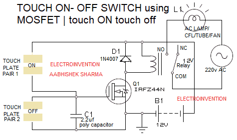
An N-channel enhancement mode MOSFET IRFZ44N is used in this circuit. 4 small metallic plates are used to make the touchpad pair. Each pair is having two copper stripes or any metallic strips with a small gap in between them. 1 pair is to turn on and the other pair is to turn the MOSFET off by touching the plates. One of the plates of Pair 1 touchpad is connected to the +ve terminal and another plate/stripe is connected to the GATE terminal. Also, one of the plates of Pair 2 touchpad is connected to the MOSFET’s GATE and the other one is connected to the source terminal. A capacitor C1 2.2uf polycap is also there between the GATE and source terminal of MOSFET.
The Drain output is connected to the relay for activating the relay operation allowing the device to be connected from AC supply.
Mosfets are very sensitive to the electrostatics.
The working logic is, when you touch plates pair 1 touch pad, it will short the +ve and the GATE due to high amplification factor of electrostatic charges through your finger allows to short them. And, the relay is activated.
When you touch second plates pair i.e second touchpad, it shorts the GATE with the SOURCE. And, the circuit is turned off.
The main properties that let this happen are MOSFET’s own characteristics. As MOSFETs are voltage-controlled transistors, touching the drain and gate terminal at the same time will short them. This will be allowing the MOSFET to turn it ON.
Touching the 2nd pair of plates, the gate and source terminal will turn the MOSFET fully OFF, due to unsatisfying voltage overdrive.
Touch Sensitive ON and OFF switch using IC 555 | Circuit 2
This is the second circuit of our touch on- touch off switch. This circuit having IC 555, an NPN transistor, a relay and a few more very useful components. So below is the circuit diagram, components required as well as working of the circuit.
Materials
- IC NE555 1pc
- Q1 BC337
- R1 3M3 ( 3.3 M ohm)
- R2 1M
- Relay 12v
- D1 1N4007
- 4 * COPPER / Metallic stripes/ plates
- Battery 12V / 12v any power source with proper regulation.
- PCB
Working
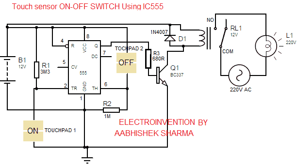
IC 555 is used to sense the touch when the finger is put between 2 plates of any of the touchpads due to skin electrostatics and moisture the IC is able to sense the touch. The IC’s PIN 4 (reset), 8(VCC) are connected to the 12v input. PIN1 is grounded.
For the ON touchpad, one end of two plates is connected to PIN 2(trigger) and another plate is connected to PIN 1 (GND). Similarly, in OFF touchpad, one of two plates end is connected to the PIN6( threshold) and another plate to the PIN8 connected to the +VCC.
This circuit’s working is based on the characteristic behavior of different PINOUTs of this IC. PIN 2 is put high by 3.3M ohms resistor and PIN 6 is put low by 1 M ohms. Two touch plates are connected to PIN2 and ground and the other two from OFF touchpad are connected to PIN6 and 8 VCC.
When the PIN 2( trigger) is held at low and PIN 6 is made low, the IC output will be high. And, if PIN 2 is already pulled high and PIN 6 also made high then the output of IC is low. If we touch the ON plates, the voltage at Pin 2 (Trigger) of the IC becomes LOW. As Pin 6 is already LOW, the output from Pin 3 gets HIGH. Then, as the BC337 Transistor’s base get the power that activates it.
The transistor then activates the relay operation, the COM(common) and NO(normally open) PIN of the relay gets shorted, the device gets AC supply.
During this, all the PIN6 is at zero voltage and PIN2’s voltage is high. After this, if we touch the OFF plates then PIN2 gets +ve for a while and the output of the 555 timer IC at PIN3 will be below. So, the transistor’s base is not getting supply and as a result, the relay is also inactivated and thus the device connected to it is also OFF.
UPDATE: Tip for better results.
Hi Aabhishek,555 is a very good ic which can be used for various types of circuits,Pin no 2 of ic should be handledVery carefully because it is very sensitive. Inthis circuit provide the touch pad always very close to pin2 of ic the touch pads should be made in small size to avoid false trigering of the ic. Better to provide pin 4 supply through a 10 k resistor and provide a 10 uf 63v cap fr pin 4 to ground. The results will be better . Regards Sambath
So, this was all about these two circuits. I hope you guys liked it. Thank you. Subscribe to our newsletter. Stay updated.
Hi Aabhishek,
555 is a very good ic which can be used for various types of circuits,Pin no 2 of ic should be handledVery carefully because it is very sensitive. Inthis circuit provide the touch pad always very close to pin2 of ic the touch pads should be made in small size to avoid false trigering of the ic. Better to provide pin 4 supply through a 10 k resistor and provide a 10 uf 63v cap fr pin 4 to ground. The results will be better . Regards Sambath
Hello Sir, thanks for visiting again. I will quote your comment in the post itself as a bonus tip. and check your mail.Thanks.
Great ideas
Hello, Thank you for visiting